No building today, we instead opted to hop on the bandwagon and go watch the movie Jurassic World with some friends and family. First time at the movie theater in a while... I think I prefer the comfort of our couches and the lack of screaming children in the theater. Seriously, who brings an infant to a thriller film about dinosaurs? </rant>
Anyway.... found out today that the ebay sellers accepted my $200 offer on the breaker panel! Exciting. Hopefully this will work as planned. If not, like I said earlier at least we'll have a stack of parts we can still use.
A question popped into my mind though that I should have thought about earlier: What happened to the Cirrus this panel came out of? I'm not a very superstitious person at all, and I guess whatever happened to this panel in a former life wouldn't really bother me too much, but it would be nice to know anyway. So I googled the tail number, N407ND, which lead me to discovering an interesting "small-world" type coincidence. Back in December ('14) a Cirrus had crashed on a go-around in Colorado, after a student pilot encountered rotor downwash from a Blackhawk helicopter that had departed just moments before. A high-definition surveillance tape caught the entire incident and made its rounds through our circle of pilot friends shortly after the occurrence (link to the video here). Lots of speculation as to how much the downwash actually played into the accident, but I'll save that discussion for another time and place. Point is, the panel I bought is out of that plane... and, the accident had no serious injuries or fatalities... cool! No bad juju. My friend Mark suggested that I should still offer rum and cigars to Jobu, just in case. Might not be a bad idea.
Monday, June 15, 2015

Sunday, June 14, 2015
Firewall - Fwd Fuse Ribs - Breaker Panel Idea
Started off this morning doing some non-airplane work in the shop, finally got around to replacing some plugs/wires/cap/rotor on one of our cars that has been needing attention for a little while. Kind of a nice change of pace getting my hands greasy under the hood of a car, it's actually been a while since I've had that opportunity :-)
Anyway once that mini-project was done it was time to clean up the garage and finish deburring/scuffing the stack of firewall/fwd fuse parts in preparation for a primer session. It's not the biggest batch of parts by any means, but there is a fairly high number of odd-shaped and small/intricate parts that take some time to deburr properly. We got through it all and by late afternoon we were ready to prime. A couple quick shots of primer brought an end to a day that felt productive enough but really didn't have much visible progress.
Only other news to report, I hopped online to get more ideas about access covers/breaker panels, and I happened to find a circuit breaker panel from a Cirrus on eBay for $270. It is exactly the kind of panel I had in mind that I wanted to build for our plane, and it comes complete with ~30 push/pull breakers, ELT panel mount, and all the buss bars and misc goodies. Even if I can't end up using it on the tunnel I've still got a goldmine of parts I can use for our electrical system, when we get to that step... at least that's the theory anyway. I put in an offer for $200... we'll see if they bite :-)
For reference, and since I don't have any pics of my own to share at this stage, here's a photo of a Cirrus breaker panel similar to the one I'm talking about:

Anyway once that mini-project was done it was time to clean up the garage and finish deburring/scuffing the stack of firewall/fwd fuse parts in preparation for a primer session. It's not the biggest batch of parts by any means, but there is a fairly high number of odd-shaped and small/intricate parts that take some time to deburr properly. We got through it all and by late afternoon we were ready to prime. A couple quick shots of primer brought an end to a day that felt productive enough but really didn't have much visible progress.
Only other news to report, I hopped online to get more ideas about access covers/breaker panels, and I happened to find a circuit breaker panel from a Cirrus on eBay for $270. It is exactly the kind of panel I had in mind that I wanted to build for our plane, and it comes complete with ~30 push/pull breakers, ELT panel mount, and all the buss bars and misc goodies. Even if I can't end up using it on the tunnel I've still got a goldmine of parts I can use for our electrical system, when we get to that step... at least that's the theory anyway. I put in an offer for $200... we'll see if they bite :-)
For reference, and since I don't have any pics of my own to share at this stage, here's a photo of a Cirrus breaker panel similar to the one I'm talking about:

We'll see if something like this can be adapted to work on the -10. If not, we should still have a handful of usable parts well worth the price paid!
Saturday, June 13, 2015
Firewall - Fwd Fuse Ribs
With summer ramping up and a few imminent plans coming up over the next couple weeks, it's going to be hard to get our daily dose of building in every day... that's ok though, productivity has always seemed to come and go in waves, and we've made it this far like that!
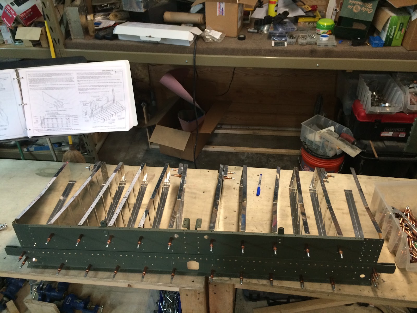
Today instead of getting right to priming, we skipped ahead to Section 28 and started prep-work on any of the parts that we could get ahead on. This way, we can have a larger batch of parts for priming and assembly. Also, I'm sort of procrastinating on the forward rib subassemblies, because I want to cut access hole(s) into them but am still undecided where they will go exactly. I think I want to make my own access cover for the right rib similar to the Airward one shown here, and maybe on the L side too. I had this crazy idea to fabricate a circuit breaker panel similar to what Cirrus has on the L tunnel, but we'll see. I think there will be a number of considerations that will have to be taken into account first... I haven't seen any other -10's with a breaker panel in that location so maybe it won't work. I'll delay riveting the L rib into place until we can make that determination, I suppose.
Anyway, today's work got us through page 28-3 step 3, which basically completes all the cutting, drilling, countersinking, and deburring of most of the small parts for section 28... should make for a good jumpstart on this section when we get there! Otherwise, it was mostly a day of staring at the fuse ribs and searching online to see what our options would be with these parts.
Today instead of getting right to priming, we skipped ahead to Section 28 and started prep-work on any of the parts that we could get ahead on. This way, we can have a larger batch of parts for priming and assembly. Also, I'm sort of procrastinating on the forward rib subassemblies, because I want to cut access hole(s) into them but am still undecided where they will go exactly. I think I want to make my own access cover for the right rib similar to the Airward one shown here, and maybe on the L side too. I had this crazy idea to fabricate a circuit breaker panel similar to what Cirrus has on the L tunnel, but we'll see. I think there will be a number of considerations that will have to be taken into account first... I haven't seen any other -10's with a breaker panel in that location so maybe it won't work. I'll delay riveting the L rib into place until we can make that determination, I suppose.
Anyway, today's work got us through page 28-3 step 3, which basically completes all the cutting, drilling, countersinking, and deburring of most of the small parts for section 28... should make for a good jumpstart on this section when we get there! Otherwise, it was mostly a day of staring at the fuse ribs and searching online to see what our options would be with these parts.
Thursday, June 11, 2015
Firewall
Took it easy the last couple days-- went to a fly-in grill-out on Tuesday (this is like the third time in a row we drove to a "fly-in"... gotta change that soon!) and hung out with some chapter 33 folks and our friend Derek who has also started on the RV-10 build journey himself! Excited that there are so many RV'ers around the area, hoping to do everything I can to help spread the "disease"! :-) Anyway, other than deburring one F-1001G gusset with Derek to show him the joys of fuselage-building after getting back from the cookout, the firewall has pretty much sat dormant since Monday's session.
Tonight, though, we got back to it. No marathon build session, but we did complete deburring, countersinking, and dimpling all holes for the firewall assembly. It was pretty straightforward for 95% of all the holes, but I was a bit confused about what to do with the 16 holes at the very bottom of the firewall that don't have any parts attached to them. The plans don't really say anything about them specifically, other than it looks like there are rivet callouts for them in the next pages. I'm thinking they must be just dummy holes that will be plugged with 4-4 flush rivets. (EDIT 6/24/15: Leave these holes alone for now! They are not dummy holes, they are used to attach the fwd floor ribs. See GOTCHA entry in this post.) Otherwise, everything was pretty straightforward... just have to watch out for two of the fourteen nutplates that need to go on the other side of the firewall, which requires different dimpling/countersinking procedures.
By the end of tonight, I believe we have a fully prepped firewall section with the aluminum parts ready for primer and all other parts ready for assembly. Should make for quick work this weekend!
Tonight, though, we got back to it. No marathon build session, but we did complete deburring, countersinking, and dimpling all holes for the firewall assembly. It was pretty straightforward for 95% of all the holes, but I was a bit confused about what to do with the 16 holes at the very bottom of the firewall that don't have any parts attached to them. The plans don't really say anything about them specifically, other than it looks like there are rivet callouts for them in the next pages. I'm thinking they must be just dummy holes that will be plugged with 4-4 flush rivets. (EDIT 6/24/15: Leave these holes alone for now! They are not dummy holes, they are used to attach the fwd floor ribs. See GOTCHA entry in this post.) Otherwise, everything was pretty straightforward... just have to watch out for two of the fourteen nutplates that need to go on the other side of the firewall, which requires different dimpling/countersinking procedures.
By the end of tonight, I believe we have a fully prepped firewall section with the aluminum parts ready for primer and all other parts ready for assembly. Should make for quick work this weekend!
Monday, June 8, 2015
Fuse Bottom Skins - Firewall
Finished riveting the fuse bottom skins tonight! There really weren't very many rivets left to do from yesterday, just a few dozen that couldn't be reached straight-on from the backside with the back-rivet set. Sarah and I bucked them in fairly short order, which put an end to Section 26... woo! Time for a photo op:


Selfie by the completed fuselage aft bottom section!

View of the completed fuse aft bottom section without us in the way
Pretty cool part of the plane! For now, this piece gets set aside and we will begin work on the forward fuselage sections (firewall, front seats etc) then eventually they all get joined together. We slid the assembly out of the way and decided it was early enough to get started on the next section, the firewall! Cleaned off the work tables, flipped the page in the plans and went parts-pickin' for the 20 or so pieces that make up the firewall assembly.

All the firewall parts prior to initial assembly
First order of business was to prepare the F-1001K Recess, which is that box-looking thing with the three holes in it in the photo above. This is our first time working with stainless steel, which the firewall and recess are made out of (the rest of the parts shown are either powdercoated steel or aluminum). Stainless steel is hard on drill bits, and has very sharp edges so we'll have to be careful with it and take our time.
Working with the recess box clamped together, we final-drilled all the corner connection holes and dimpled everything so that the flush side of the rivets will be facing forward. The plans mention that dimpling one of the #30 holes will be difficult because it's near an edge, and recommended using a female dimple die and a #4 flush rivet. I ended up having to cut the rivet down quite a ways to do this, and used a bucking bar on the flush side and rivet gun attached to the female die on the other side:

Our specialty dimpling setup consisting of a female dimple die, a chopped-down #4 flush rivet (basically like an AN426AD4-1), and a bucking bar. The offending hole (already dimpled) is at the upper right of the photo above.
Looks like we'll need to use this setup on four more holes on the firewall itself, but that's for later (I peeked ahead in the plans). Anyway with the recess deburred and dimpled, a quick dozen rivets later it was assembled into the box it needs to be to proceed with assembling the rest of the firewall for final-drilling. Clecoing all the parts together was actually a bit more frustrating than I had imagined-- many of the aluminum pieces either fit into each other or overlap in some way with very close tolerances. Plus, many of the holes (especially with the powdercoated parts) weren't quite big enough for a cleco to pass through easily and/or didn't line up perfectly with the underlying structure. In time, I was able to get it all together though, it just took a bit more coercion than I had expected.

The F-1001 Firewall clecoed together, ready for final drilling

Side view of the firewall
Pretty cool piece! Definitely some very strong components in here, at the four corners for the motor mounts and then in the lower middle to support the nose gear. With everything together it made for a fairly quick final-drilling session, after which the clecoes behaved much more nicely holding everything together. Next step is to pull it all back apart for more deburring, dimpling, countersinking, scuffing and priming (aluminum parts only of course)... and then rivet it all together!
We'll save that for another day.
Sunday, June 7, 2015
Aileron Actuation - Fuse Bottom Skins
Got another "to-do" checked off on the wing section today... yay! Finished the Aileron Actuation section today, which was a pretty cool section to work on. Previously, we had already created a few pushrods and bellcranks but not the torque tube assemblies, so it was time to get started on that:


Clocking/assembling the aileron torque tube assemblies - 5/16" offset and 17-3/4" total length (+1/32" acceptable)
One of the brackets needs to have a 5/16" clocking with respect to the other, as written in the plans. I decided to use a 5/16" drill bit (shown above) as my reference for clocking since it has a very precise "known" size. It went pretty smoothly and before I knew it I had two mirror-image torque tube assemblies. Now to prime and install on the wings. Installing them between the two torque tube bearings was actually was trickier than I thought it would be; there really isn't much room to work the pieces around, and the fact that the pieces have now been primed means they are even more reluctant to slip into one another. Eventually though, I prevailed and ended up with these torque tube assemblies installed:

R Aileron Torque Tube assembly

L Aileron Torque Tube assembly
With these installed, it was time to put the rest of the works together! This was exciting, because when complete you can push/pull on the levers here on the torque tube, and see the ailerons go up and down, way over on the other side of the wing... like magic! So, a few bolts/nuts/washers later, I had the following assembly together:

Torque tube -to- pushrod joint

Aileron bellcrank assembly with two pushrods
By golly it works! Awesome. Played with the ailerons, moving them back and forth for a longer period of time than someone my age ought to have. Oh well, no one was watching. We'll still need to final-rig these bearings at a later time for all the correct tolerances once everything is together, but they certainly appear close to the recommended clockings and everything moves smoothly and precisely! Very cool, couldn't be happier.
After Sarah got back from her afternoon plans (which included tearing up the skies over Marion in a C150, I might add), we got back to back-riveting the fuselage bottom skins. It's a fun process but gets pretty tedious after a few hundred rivets. We persevered through it all though, and I'm pleased to say that all back-rivetable rivets are now back-riveted! There's still a few dozen here and there that we skipped over to get later via the traditional flush-riveting method. Maybe tomorrow we'll get to that. No pics of the fuse in its current state yet, we're saving the "reveal" for when we get those last rivets done... hopefully tomorrow!
Saturday, June 6, 2015
Baggage floor ribs - Fuse Bottom Skins
A quick primer session later, we were ready to install and rivet the baggage floor ribs. Since there are only six of them (as opposed to 12 under the back seat) this effort went, well, twice as fast as the last riveting session, and we had a surprisingly big piece of the fuselage skeleton staring back at us:


Baggage floor ribs attached!

Side view of fuselage aft skeleton complete!
This was definitely pretty exciting. It's easy to see the area that the backseat passengers will sit in, buckle up into, where they will put their feet, and even where they will get hot air from the heater! Pretty neat stuff. Anyway, now that the skeleton is complete, it's time to start with the fuse bottom skins. These are two giant sheets of aluminum with a million holes that go over the bottom of everything we've just created. Time to cleco it into place and get to match drilling!
For some reason, I didn't snap any photos of the skin match-drilling process, but suffice it to say that it is very much like the wing top/bottom skin endeavor, where you have a ton of holes and just need to do your best to keep track of which holes are "done" and which ones still need attention after shuffling clecoes around. Since we're well versed with this process, it really wasn't too bad but it did take many hours (and several drill battery swaps) to complete. By the end of it though, we had a drilled and deburred set of skins, and a skeleton to match. Now, just to scuff, dimple, and prime... why not move right along to it?!

The ol' Mikey J 2000 slaving away on the bottom skins
Unbelievably, we were actually able to get through the fuselage bottom skin prepwork in ONE day... wow! This included final-drilling, deburring, scuffing, dimpling, and priming a very large number of holes in the skins as well as the substructure. With all that progress made, we had to at least get started on the riveting process, just to say we did :)

Finally, a picture of the bottom skins and the whole assembly together... ready for riveting! Sarah says it looks like a tick... I think I see it.
So, we didn't do a bunch of riveting but we did enough to feel accomplished... we got through all the floor stiffeners and mid fuse seat ribs that could be back-riveted, which is almost all of them. Still plenty more to go though!

Hardly looks like any rivets have been done yet!
Tomorrow we'll continue with the riveting as time permits, Sarah has some stuff going on so in her absence I might go back to do some aileron actuation too, who knows?
Friday, June 5, 2015
Rear Seat Ribs - cont'd
A slow day at work today allowed for an extended lunch hour and some great progress on the fuselage for a weekday... awesome kickoff for a hopefully productive weekend! I was able to rivet the rear spar bulkhead to the center section/seat rib subassemblies, and then all 12 rear seat ribs to the rear spar bulkhead. The resulting assembly looked like this:


Once those were done, I couldn't think of a single reason not to cleco the last bulkhead and baggage floor ribs onto this rapidly-budding fuselage!


Holy cow... It's starting to look like a backseat!

R side view of the back seat ribs after riveting

L side view of the back seat ribs after riveting

Aft bulkhead and baggage floor ribs clecoed into place for match drilling

10 minutes of work yielded 33% increase in apparent size... wow!
Got some final-drilling done on these parts too, but then discovered an issue: one of the baggage floor ribs had a crack in its lightening hole flange. I assume that this comes from when the part is stamped out of raw material at the factory, and for whatever reason this piece split just a little bit. Here is a closeup of the affected area:

Spotted a crack in the aft-most hole of the F-1020-R baggage floor rib
I decided to call Van's builder support tonight (they have a morning window and then a 1-hr window from 5:30-6:30pm local time to call and talk directly with the 'mothership' builders) and report the issue and ask for guidance. I assumed that I could stop-drill this crack and be good to go, but wanted to make sure before doing anything. I got the good news I had hoped for; this apparently does happen from time to time during the manufacturing process, especially with the 2024-T3 aluminum material that this is made of, and it's no huge issue for concern. The builder I spoke with confirmed that sanding the area out (if it is small) or stop-drilling the crack (if it is larger) is the correct and perfectly acceptable repair for this kind of defect. So, a quick zap with a #40 bit and EZ-Burr yielded this repaired part:

Stop-drilled crack in flange

Other side of flange, it is apparent the crack was not square with the material but the stop-drill covered the area just fine.
It was a bit disconcerting to have a "defective" part (or at least "a part containing a defect") shipped as part of the kit... but after examining all the rest of the ribs and considering exactly the problem found and the solution implemented, we were put a bit more at ease. The only thing we really care about is that this crack does not propagate past the flange and into the rest of the rib. Thankfully, both the crack and the stop-drill are contained within the area of that flange, and therefore essentially no structural integrity is lost.
With that minor setback behind us, it's time for more priming and assembly.... tomorrow!
Thursday, June 4, 2015
Rear Seat Ribs
Flipped the page to the next portion of this section, the rear seat ribs! This part consists of twelve ribs that go aft of the rear spar bulkhead and are directly under the rear seat. Time to get the rear spar bulkhead out and start clecoing/match drilling!

The Rear Spar Bulkhead assembly with Rear Seat Ribs clecoed together
The process starts with separating/making four seat belt attach points that go on four of the 12 ribs, otherwise it's a really simple and straightforward process of drilling and deburring. After a quick visit with the deburring tool, a file, and the scotchbrite ball, it was ready for primer! A quick and easy priming session closed the night out, tomorrow we should be ready to assemble the ribs to the bulkhead!
Tuesday, June 2, 2015
Mid Fuse Ribs
No building yesterday due to a sick dog and some last-minute things that came up, but tonight we're happy to see Dag doing a lot better and got some more great progress on the fuselage. I hate to say this so early on in the fuse build, but this is definitely some of the most fun building we've had so far... most of the steps are pretty short bursts between prep work, priming, and riveting so it really feels like a lot is getting accomplished in a short period of time! Hardest thing about all of this is reading/following the plans properly... more on this later.
With the inboard seat rib subassemblies match-drilled and complete, we moved on to do basically the same kind of work for the outboard seat rib assemblies. One word of caution: the side of each piece that you are supposed to dimple is different between the outboard and inboard ribs, and without staring at the plans for quite some time this is an easy detail to miss. I *almost* dimpled the outboard ribs backwards but caught my mistake just in time. Anyway, with the inboard and outboard assemblies drilled, deburred and scuffed, it was time for a quick primer session:


With the inboard seat rib subassemblies match-drilled and complete, we moved on to do basically the same kind of work for the outboard seat rib assemblies. One word of caution: the side of each piece that you are supposed to dimple is different between the outboard and inboard ribs, and without staring at the plans for quite some time this is an easy detail to miss. I *almost* dimpled the outboard ribs backwards but caught my mistake just in time. Anyway, with the inboard and outboard assemblies drilled, deburred and scuffed, it was time for a quick primer session:

F-1016 inboard/outboard seat rib subassemblies
Next, it was time to rivet these assemblies together, which overall went pretty well. I did end up having to drill out two rivets along the bottom of each of the outboard rib assemblies though, because the plans weren't very clear (in my opinion) about which side to place the manufactured head of the rivet. One diagram shows the rivet callouts, which is typically all you need, then only in a later diagram there's an arrow saying "shop head on other side"... thanks for that! Woulda been nice to know earlier. No major foul, everything drilled out perfectly and after redoing them you'd never know what happened. I'd say in general, the plans are most definitely starting to assume you not only "know what you're doing" but also know how to read their plans-- which, depending on what section you're working on often requires the elusive skill of divination. I'm still working on that one myself.
Anyway, after a bit of riveting we had all four assemblies... assembled.

The inboard (bottom) and outboard (top) seat rib subassemblies.

Other side of the subassemblies. Sorry for the bad photo.
With these ribs riveted together, it was time to put together the flap motor brackets, which only involves basically three more pieces and a vent tee. Although they were a bit tricky to align and drill, it was quick work to drill and deburr everything and get the two inboard halves mated, shown here:

The flap motor attach brackets and vent tee installed between the inboard seat rib assemblies
After that, it was time to attach the whole works together, to the Aft Center Section Bulkhead! This was an exciting step because it's the first time the parts are coming together to build the first "three dimensional" part that will essentially make up the floorpans for the rear seat passengers. After a few match-drills, deburrs, bolts, and rivets, we had this:

Completed seat rib/aft center section subassemblies

R side view of the fuselage so far
With that, it was time to call it a night... next up, the rear seat ribs! From the looks of it in the plans, there are 12 ribs that go under the back seat, so I see lots of fluting and deburring in our future (see, I'm getting better at that whole divination thing)!
Subscribe to:
Posts (Atom)