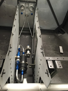
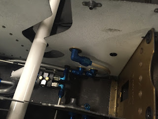
Brake lines and brake valve in tunnel
Brake lines terminated on firewall
Parking brake valve with control cable mounted in place.
Demonstrating the clearance between the elevator/aileron controls and the brake valve/control assembly. In a worst-case scenario with the aileron control rod touching the bottom of its cutout, there is still about 1/4" between it and the clevis for the parking brake, which itself is in a "parking brake ON aka on-ground-only" position. The elevator control passes over the top of the valve with at least an inch or so of clearance.
This location for the parking brake valve should work fine... at least that's what I'm thinking so far. Next up was to start making components for the fuel system in Section 37. Since I'm "rolling my own" boost pump and return line, and also moving the fuel selector forward about 6" to make room for the armrest throttle quadrant, the fuel line measurements in the plans will be of little use other than to use as a general guide. The first thing to do is actually build the boost pump module, which I did by making two U-shaped pieces of 5052-O 3/8" aluminum tube:
Check valve (left) and boost pump (right) connected via two U-shaped tubes and fittings. Inlet is at the bottom tee, outlet is at the top.
The black jacket over the pump is an insulation sleeve I found online for fuel pumps, and it should help the pump run both cooler and quieter. Next, I started with the task of mounting the pump assembly and the pressure relief valve into the tunnel. Sarah and I riveted the two little pump mount brackets to the forward fuse bottom skin (deferred from way back in Section 28) in their normal locations. We had held off on riveting these before because we wanted to make sure we could make use of them and wouldn't have to relocate them or make a custom bracket. It turns out the standard locations work great, and we can put the boost pump module in the aft and center location, with the pressure relief valve in the forward location. This means the "send" line will exit the firewall on the L side of the firewall, and the "return" line will enter the firewall on the R side. So, with this plan in mind, I got to work getting it all installed.
Boost pump module installed in tunnel. Pump is secured via the standard hose clamp mounting method, and the check valve is secured to the L tunnel side with an adel clamp and #8 flush screw.
Larger view of the forward tunnel area, with both fuel Send (L) and Return (R) fittings visible below the heater outlets.
Next, more 3/8" 5052-O tubing had to be bent and installed between the firewall and the modules, as well as one run going back to a fitting on the rear R tunnel wall that will be the aux tank fill inlet. This line will be plumbed to a small panel in the rear seat area accompanied by a vent line and electrical connection. When an aux tank is installed, we'll be able to flip a switch on the panel to turn on a transfer pump inside the aux tank which will feed fuel to the fuel return line downstream of the pressure relief valve, allowing fuel to be fed into either the R or L fuel tanks, depending on the fuel selector.
Aux fuel inlet line visible above the rest of the fittings, with line swooping aft and then below the rest of the brake and fuel fittings. Also visible: tunnel entry points for fuel return and brake lines.
Aft tunnel area with everything installed
Forward tunnel area with everything installed
Boost pump module and pressure relief valve assembly close-ups. The taped-off fitting on the upper left side of the photo is the fuel inlet (from fuel selector send outlet), and on the bottom center is the fuel return outlet (to fuel selector return inlet).
Overview of the tunnel area from the firewall looking aft
That's pretty much it for today! Lots of good progress. The astute observer may notice a lack of pipe thread sealant on the exit side of the pressure relief valve, where there is a reducer and tee fitting for the fuel return and aux feed lines. I'll need to pressurize the system once and double-check the pressure setting for the relief valve, as it can be adjusted via a hex key inserted through this end of the valve. I figured it would be worth it to not seal these threads yet since they will likely be coming back off again anyway.
Other than that, I took some measurements for the stainless braided lines I'll need to buy to go from the tunnel entry points in the rear of the tunnel and up to the fuel selector, and also the two lines coming from the selector to the send and return lines. Until I can get them ordered and delivered, it's on to something else... maybe priming and assembling the back seats? We'll see!


