Haven't posted an update in almost a week! Oops. It's been a weird few days... not that we haven't been working on the plane, but we haven't really made much visible or reportable progress on any one thing.
We'll cough up the non-building excuses first: Thursday last week we flew the Archer from KIIB up to KMCW for a "Third Thursday" cookout and met up with our friend Martin in his Bonanza. Had a great time up there as usual and then flew down to Marion to hangar the plane near home for the weekend. I've been working off-and-on on a side-project for my dad also that's been taking some time. Yesterday morning I participated in my first Young Eagles event as part of our local EAA chapter hosting an airport staff/friends/family event at KCID. There wasn't a huge turnout, only maybe a dozen families at most for 10 planes, so I only took one passenger load-- a mom and her ~11 year old daughter. The mom seemed to have fun but unfortunately the little girl didn't enjoy her first ride in a plane as much as I had hoped she would. It was a bit bumpy out that morning, and some of the gusts even caught me by surprise a bit. So, after a quick shot over downtown Cedar Rapids we made a quick dash back to the airport with a teary-eyed girl in the backseat :-( Oh well, at least no one got sick... Hopefully the next event will yield more visitors, smoother air, happier passengers, and inspire some future pilots!
On the days in between all that though, some decent progress was made. I deburred and dimpled all the parts that Derek and I prepped last Tuesday. I rebuilt my "tailwheel" to be a bit more robust and have the tail sit a bit higher so the fuselage is more level. I've begun work on my instrument panel to try and figure out what is going to go where. So far, here's my plan for the panel. Aside from some lights and switches, there will be four "big ticket" items on the panel itself: A dual-screen 10" G3X Touch system, GMC307 control panel, and GRT Mini-X as a backup EFIS. On the lower center console, I'll put my audio panel and navigators, possibly one or two GNS430W's, or an SL30... or if I win the lottery a GTN750/650 stack. We'll see. It's sort of depressing how expensive this stuff is. Even obsolete units are many thousands of dollars. Never thought that "going cheap" still meant spending $20k! Ha. Regardless for what I end up with though, there should be room for any of the above, so we're good there.
In addition to the above, I also made cutouts in the fuse bottom skins under the steps for some access panels. I realize most people put access covers in the baggage floor on the inside and not on the outside, but I wanted to do this a bit differently and also equip the cover with puddle lights to illuminate below the steps. Hopefully that all goes to plan. My Panduit solid corrugated tubing arrived from CableOrganizer.com. I'll be running two 1" tubes from aft of the baggage area to forward of the rear seats, past the new access holes and the steps. Speaking of the steps, I got them back from the powdercoaters, they look awesome! I also received my TCW Step Bushings in the mail, so I think we're getting pretty close to buttoning up the first half of Section 33 (the second half requires you to have the rear seat and baggage floor panels installed... which requires steps to be installed and wiring conduits run).
Lastly, I've started dabbling all over the plans, working on section [mumbles]30-something. Started on the baggage door. Started planning for the fuel and brake lines, location of the parking brake valve and fuel selector valve, and tallying all the lines and fittings that need to be made. Pestered Paul Grimstad at Control Approach one more time about his rudder pedal system. He's working frantically on getting a prototype completed and will be ready to ship "soon". I've got plenty to work on before I "need" them for sure but I'd like to get them here sooner rather than later if possible. Started on the access covers and floor panels section, particularly for the tunnel cover. Got a few random parts in the mail including a clear brake reservoir (Matco) and a ground power connector (Cessna-style).
All of this feels like I'm going in 100 different directions and nothing is complete yet. There are a lot of inter-dependencies on things being complete before work can start on the next thing, etc etc. Hopefully a lot of that will get sorted out in the coming week. Until then... maybe we'll have some pics and noteworthy progress in our next installment!
Sunday, August 23, 2015
Tuesday, August 18, 2015
Upper Forward Fuse - Baggage Area
Yesterday I had a brief session in the factory to remake the F-1044B angle that I had mis-drilled last time. I actually ended up doing this twice, because I messed up my first remake. Third try was the charm though, and so now in addition to the usable part I have two 17-5/16" long pieces of aluminum angle that I'm 100% certain will get put to good use on some future part of the plans. Not ideal, but oh well that's the way it goes sometimes. At least I didn't have to reorder any parts I suppose.
One other bit of news from yesterday, I called Van's to place my order for the finish kit! They are quoting an 8-week lead time, and although I'm pretty sure I won't be *done* with the fuselage in 8 weeks, it will be nice to have some of the parts contained in that kit a little ahead of time. I have a few weeks now to finalize a "delete" list and send in to them. I'll cover this in a future post.
In the meantime though, tonight it was time to start on the task of deburring all the upper forward fuse parts. It actually went pretty quick using the EZ-Burrs on all the drilled holes and the belt sander for all corners and edges. I started dimpling a few of the smaller parts, but got bored of it and started thinking about how I won't really be able to get too much further with all these parts until I figure out my panel layout a little better. So, I tossed the pile of parts back into the shelf and will continue with that as we get closer to section 41 where it all actually has to be attached permanently (Section 31 is sort of designed to be an "at your own pace" section and allows you to slowly put your panel together outside of the airframe and then attach the whole works in section 41).
Shifting gears to Section 33 then (remember 32 is tailcone attach, complete!), we began work on the rear seat and baggage floor areas. I won't be able to final-install the floors yet before we get the steps back from powdercoating and I finalize my antenna layout, putting any necessary doublers under the back seats... but that won't stop us from prepping all the parts!
Derek came over tonight to help out, and we had a mega-productive session match- and final- drilling the floor covers. We started off with the back seat floors and moved aft to the baggage floors per the plans, which included cutting some AN257-P3 hinges to size and match-drilling them to the panels. The hinges will be used to attach the rear seatbacks to the airplane, and allow for removal by simply pulling the pins out. I took charge of the L side of the airplane, and Derek took the R side (Sarah took a "supervisory" role tonight). With two drills and two cleco pliers going, we made quick work of it all!


One other bit of news from yesterday, I called Van's to place my order for the finish kit! They are quoting an 8-week lead time, and although I'm pretty sure I won't be *done* with the fuselage in 8 weeks, it will be nice to have some of the parts contained in that kit a little ahead of time. I have a few weeks now to finalize a "delete" list and send in to them. I'll cover this in a future post.
In the meantime though, tonight it was time to start on the task of deburring all the upper forward fuse parts. It actually went pretty quick using the EZ-Burrs on all the drilled holes and the belt sander for all corners and edges. I started dimpling a few of the smaller parts, but got bored of it and started thinking about how I won't really be able to get too much further with all these parts until I figure out my panel layout a little better. So, I tossed the pile of parts back into the shelf and will continue with that as we get closer to section 41 where it all actually has to be attached permanently (Section 31 is sort of designed to be an "at your own pace" section and allows you to slowly put your panel together outside of the airframe and then attach the whole works in section 41).
Shifting gears to Section 33 then (remember 32 is tailcone attach, complete!), we began work on the rear seat and baggage floor areas. I won't be able to final-install the floors yet before we get the steps back from powdercoating and I finalize my antenna layout, putting any necessary doublers under the back seats... but that won't stop us from prepping all the parts!
Derek came over tonight to help out, and we had a mega-productive session match- and final- drilling the floor covers. We started off with the back seat floors and moved aft to the baggage floors per the plans, which included cutting some AN257-P3 hinges to size and match-drilling them to the panels. The hinges will be used to attach the rear seatbacks to the airplane, and allow for removal by simply pulling the pins out. I took charge of the L side of the airplane, and Derek took the R side (Sarah took a "supervisory" role tonight). With two drills and two cleco pliers going, we made quick work of it all!

The back seat floor covers after match-drilling

The L baggage floor cover with hinge clecoed into place

Derek match-drilling the hinge to the R baggage floor cover
We finished the night off by making the F-1022 B-G stiffeners and final-drilling them to the R and L baggage floor skins. Derek did an awesome job cutting all 12 pieces from the two provided long aluminum angles using the bandsaw and belt sander to clean them up! While he was doing that, I went ahead and deburred all #30 holes in the four floor panels, leaving only the #40 and #19 holes to finish up.
Great night of productivity! It really feels like things are kicking into high gear, and I can't wait for this thing to be ready to fly!! Gotta keep my excitement in check though, still got quite a ways to go... it's hard to imagine that we're really only about halfway done at this point... probably not even half!
Sunday, August 16, 2015
Center Console
Today I started on a rough-cut of a home-brew center console I want to make. Instead of putting the throttle/prop/mixture controls up on the panel like many RV's, I want to put mine down on the tunnel, closer to the armrest, and then use the center console area for a radio stack, switches, etc. The general idea came from a photo I saw of Greg Hale's famous (perhaps infamous) RV-10, N210KH:

Greg Hale's RV-10
Say what you want about some of the other modifications he made to this aircraft, but the interior is stunning. Van himself wrote a fairly scathing review of this airplane, visible here (link). I actually spoke to Van at Oshkosh this year and thanked him for writing that article, because I believe it has helped me resist many of the temptations that are out there to go balls-to-the-wall with modifications and not realize the safety implications of changing major parts of the design. I highly recommend reading that article if you haven't already. Anyway.... back to the interior and center console, which has steered clear of that sort of scrutiny. Although I'm not personally a fan of the color or wood grain trim, and I'll have a slightly different avionics configuration, I do like the general form and layout of this panel, and will use this as an inspiration for my own less-fancy design. Off to the workbench to further my metal-forming skills!
The tunnel cover is about 5.5" wide and 10.5" down underneath the front of the panel and slowly expands to 6.5" wide about a foot further forward under the panel. The sides of this center console need to be at least 6.3" wide in order to fit a radio stack. So, I took two pieces of 0.032" aluminum sheet and made matching conical bends (basically a mini-version of what was done to the mid fuse skins) to attach to the tunnel covers, and then bent them outwards at the top to "flow" into the panel. I made a temporary jig out of hardware-store aluminum angle to keep both pieces square and straight and clecoed it all into place:

Rough-cut of the center console
Looks good so far! Well, it looks "ok" so far. Good from 10 feet, but still have quite a bit of trimming and tweaking. For the most part it is square and centered, and at a 6.5" width it should accommodate a radio stack quite well. The filler pieces inside there are only temporary as described above, and ultimately it will just be a 6.5" x ~10.5" cavity to flush-mount my GPS's (i.e. GTN650 etc). Covered with upholstery and everything, it should look pretty slick. I hope, anyway.
That's pretty much it for today! As any builder will say, once you start going off the plans to make stuff like this, it takes 10x as long. Tomorrow I'll probably get around to fixing yesterday's goof with the F-1044 angle, and maybe start on the baggage compartment section!
Saturday, August 15, 2015
Tailcone Attach - Cradle - Upper Fwd Fuse - Section 32 Complete!
Today was one of those "builder's dream" productivity days! It actually started last night when I finished a few of the rivets that I could reach myself for the tailcone attach. I was actually able to reach almost all of the rivets on both sides and that attach the ribs and bulkheads, but still needed Sarah's help to finish the ones along the bottom. While I waited for that, I figured it was time to get the fuselage off of my work tables and set it on the ground in its own cradle. I set out to build those, and what I ended up with is pretty close to other ones I've seen online:


The front legs are basically just 16" long 2x6's with holes match-drilled for one big and one small hole in the center section bulkhead. Basically working from inboard to outboard, the holes go "SBBS": I have one small and one big wing attach bolt in positions #1 and #3, and then these 2x6's are attached at positions #2 and #4. I had to scoop out little reliefs on the inside faces of the 2x6's to make room for the wing attach bolt heads, which took a bit of time and head-scratching, but I eventually prevailed using a bit I had laying around from when I made my computer desk in the drill press: the kind of bit you use to install recessed hinges in cabinet doors.
Hardware-wise, I used 4x 1/2" x 8" bolts in the "big" holes and 4x 5/16" x 8" bolts in the "small" holes. I had originally bought 3/8" bolts for the small holes, but silly me, they were too big. In the photos above, I hadn't yet made the exchange so you only see the big bolts in place.
For the tail wheel, I padded some 2x6's to hug the end of the tailcone, and ran a single 3/8" bolt up into the tie down hole, tightened only to be "snug". It worked but it wasn't super stable if you put a lot of weight in the tail, so I ended up rigging a little 2x4 arm to come forward and rest against the bottom skin a foot or two ahead of the attach point. The arm is held tight against the bottom skin with a tiedown strap. A little ghetto but hey it works. And there you have it!
At about this time, Sarah came out and we finished riveting the bottom rivets between the tailcone and fuselage. That puts an end to Section 32... yay! I'm liking these few-day-long sections as opposed to the few-week-long sections like 29. :-)
Next on the agenda was the Upper Forward Fuse assembly, Section 31. This section is relatively straightforward and starts off like many of the other sections fabricating some small aluminum pieces for who-knows-what and then as you start to cleco things together it all starts to make sense. I snapped a photo of the first step:

Interestingly, this piece that I fabricated played a co-starring role in a minor goof-up I had today. As you begin to assemble the different pieces, there was one kind of odd thing they have you do, which is to match-drill the F-1044B angle into a brace on the firewall by drilling "up" through the firewall recess (they first have you drill a pilot hole "down" from the brace through the recess). Kind of an interesting process. Anyway, the goof-up was that I forgot to put the F-1044C spacer that I had just so proudly fabricated into place, so the hole drilled through the F-1044B angle isn't in the correct location. Oops! I'll have to toss the piece and make another one. Oh well, should be a zero-sum game in the end, I have plenty of extra aluminum angle sitting around. For now, I decided to continue with assembling the rest of the assembly for match- and final- drilling:


She's on her own feet for the first time! (albeit with temporary shoes... err maybe wooden clogs)

Presenting the RV-10 taildragger!
The front legs are basically just 16" long 2x6's with holes match-drilled for one big and one small hole in the center section bulkhead. Basically working from inboard to outboard, the holes go "SBBS": I have one small and one big wing attach bolt in positions #1 and #3, and then these 2x6's are attached at positions #2 and #4. I had to scoop out little reliefs on the inside faces of the 2x6's to make room for the wing attach bolt heads, which took a bit of time and head-scratching, but I eventually prevailed using a bit I had laying around from when I made my computer desk in the drill press: the kind of bit you use to install recessed hinges in cabinet doors.
Hardware-wise, I used 4x 1/2" x 8" bolts in the "big" holes and 4x 5/16" x 8" bolts in the "small" holes. I had originally bought 3/8" bolts for the small holes, but silly me, they were too big. In the photos above, I hadn't yet made the exchange so you only see the big bolts in place.
For the tail wheel, I padded some 2x6's to hug the end of the tailcone, and ran a single 3/8" bolt up into the tie down hole, tightened only to be "snug". It worked but it wasn't super stable if you put a lot of weight in the tail, so I ended up rigging a little 2x4 arm to come forward and rest against the bottom skin a foot or two ahead of the attach point. The arm is held tight against the bottom skin with a tiedown strap. A little ghetto but hey it works. And there you have it!
At about this time, Sarah came out and we finished riveting the bottom rivets between the tailcone and fuselage. That puts an end to Section 32... yay! I'm liking these few-day-long sections as opposed to the few-week-long sections like 29. :-)
Next on the agenda was the Upper Forward Fuse assembly, Section 31. This section is relatively straightforward and starts off like many of the other sections fabricating some small aluminum pieces for who-knows-what and then as you start to cleco things together it all starts to make sense. I snapped a photo of the first step:

The F-1044C Spacer - And my feet.
Interestingly, this piece that I fabricated played a co-starring role in a minor goof-up I had today. As you begin to assemble the different pieces, there was one kind of odd thing they have you do, which is to match-drill the F-1044B angle into a brace on the firewall by drilling "up" through the firewall recess (they first have you drill a pilot hole "down" from the brace through the recess). Kind of an interesting process. Anyway, the goof-up was that I forgot to put the F-1044C spacer that I had just so proudly fabricated into place, so the hole drilled through the F-1044B angle isn't in the correct location. Oops! I'll have to toss the piece and make another one. Oh well, should be a zero-sum game in the end, I have plenty of extra aluminum angle sitting around. For now, I decided to continue with assembling the rest of the assembly for match- and final- drilling:

The "subpanel" and three ribs clecoed to the forward fuselage. The errant F-1044B angle (accidentally sans F-1044C spacer) is visible attached to the middle rib.
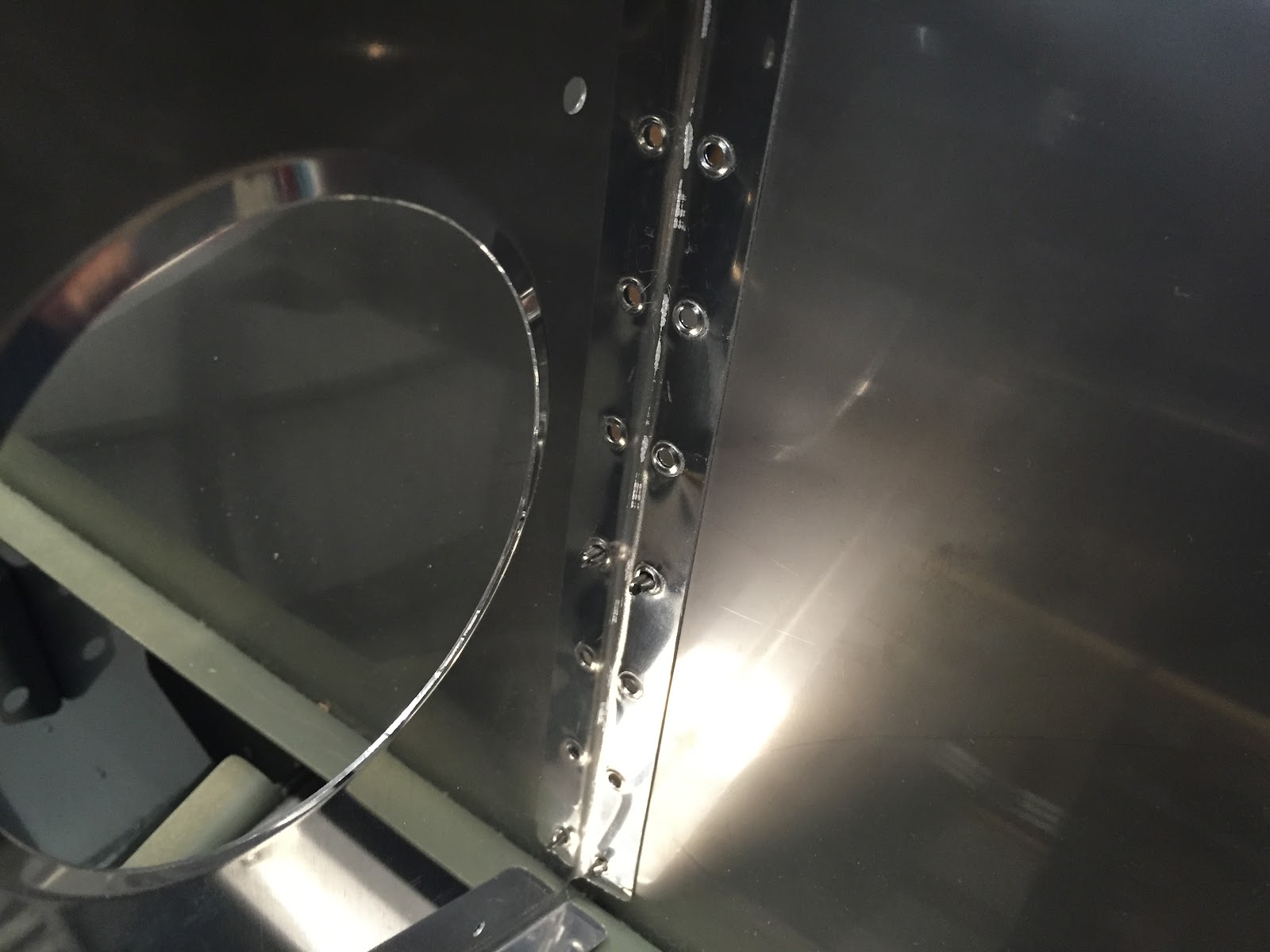
For a while, I thought this F-1044A center rib might have been formed incorrectly at the factory-- the holes in the forward flange are much closer to the web than normal and were a PITA to dimple. They are correct though!

Right side of subpanel

Forward top skin clecoed into place for final-drilling!
This makes the airplane instantly look super-neat (as if it's not already super neat-looking, anyway). It's easy to get lost just staring at the thing and watching the time go by. However, I resisted that temptation and proceeded with all the necessary drilling tasks. The focus then shifted to the inside of the cockpit now, where the last drilling task remained: match-drilling the F-1003D/E flanges. These pieces start life as 0.032" aluminum angles and must be fluted to match the contour of the top skin, ensuring that no flutes are made where the instrument panel attach holes are. This proved a bit tricky but in the end wasn't all that bad. After that though, you have to hold the pieces up under the panel and match-drill down (towards your fingers!) into the angle. It was a bit of a sticky situation but ultimately I only had one "close encounter" with a drill bit poking through, and no blood was shed during that battle. Whew!
That's pretty much it for tonight! Tomorrow I think I'll start on an idea I have for a center console to go between the panel and tunnel... stay tuned!
Thursday, August 13, 2015
Tailcone Attach - Static Ports
The tailcone attach section is going a lot more quickly than I thought it would! Finished final- and match-drilling the various parts between the fuselage and tail section, and before long the two halves were separated again for deburring, dimpling and countersinking. There were a small handful of parts that needed priming, including some parts around the baggage door, both mid fuse longerons (I had previously left them only clecoed into place until this section could be completed) and the F-1006 bulkhead parts which I didn't prime or rivet together during the empennage construction to simplify things a bit.
While the primer was drying, I wanted to finish one relatively small task that would be much easier to complete now before the tail gets attached-- installing the static ports. I've decided to go with the SafeAir static ports and plumbing lines, which I've had on hand for some time now but haven't done anything with. Looking through the instructions, installing the ports appeared to be a lot easier than I was thinking it was going to be. You have to enlarge the small pilot hole in the tailcone side skins to 1/4" in diameter and then mount the static ports from behind. The port, with its angle attachment and adapter for air hose, looks like this:

To actually mount the port, you have a few options. Many builders choose to rivet the ports into place, which would be fine except I'm not a huge fan of dimpling the middle of a large piece of skin once it's already been installed. It can be done, but it's time-consuming, nerve-wracking, and never seems to produce the same quality dimples you can do on the bench. The second option is to adhere the part from the back with proseal or some other adhesive. I chose this route and actually just used standard epoxy resin to install these.
I first traced a circle on the inside of the skin to mark where the port will actually mount, and then removed the primer on the skin from this area using a dremel with wire wheel brush. Cleaned the area up a bit with some acetone (carefully!) and then scuffed up the face of the port with some sandpaper, making certain to not scuff up the actual "nipple" on the port itself. Cleaned both surfaces again, this time with alcohol, let it dry quickly and applied the epoxy to the static ports, again making sure to keep it away from the nipple. Then I stuck them into place and held firm with some masking tape. Hopping out of the cone to the outside, I then cleaned up any excess adhesive with alcohol. After the epoxy cured, I installed a tee fitting into an existing hole in the bulkhead and ran the air lines to it. The result came out pretty good!


While the primer was drying, I wanted to finish one relatively small task that would be much easier to complete now before the tail gets attached-- installing the static ports. I've decided to go with the SafeAir static ports and plumbing lines, which I've had on hand for some time now but haven't done anything with. Looking through the instructions, installing the ports appeared to be a lot easier than I was thinking it was going to be. You have to enlarge the small pilot hole in the tailcone side skins to 1/4" in diameter and then mount the static ports from behind. The port, with its angle attachment and adapter for air hose, looks like this:

SafeAir static port with 90-degree air hose fitting
(photo stolen from online, I forgot to snap a picture of mine prior to installation)
I first traced a circle on the inside of the skin to mark where the port will actually mount, and then removed the primer on the skin from this area using a dremel with wire wheel brush. Cleaned the area up a bit with some acetone (carefully!) and then scuffed up the face of the port with some sandpaper, making certain to not scuff up the actual "nipple" on the port itself. Cleaned both surfaces again, this time with alcohol, let it dry quickly and applied the epoxy to the static ports, again making sure to keep it away from the nipple. Then I stuck them into place and held firm with some masking tape. Hopping out of the cone to the outside, I then cleaned up any excess adhesive with alcohol. After the epoxy cured, I installed a tee fitting into an existing hole in the bulkhead and ran the air lines to it. The result came out pretty good!

The static air port after installation

Inside view of static system ports and air lines... ready to run to my ADAHRS!
Once this was done, I riveted the Mid-Fuse longerons into place which was maybe a couple dozen rivets per side and didn't take too terribly long. Then the "momentous moment" was upon us: mate the fuselage and tailcone for good!

The last time we see the tailcone by itself

Riveted the F-1006 bulkhead to the tailcone (this is the opposite from the previous time they were joined, where you cleco this bulkhead to the fuselage)

Final moments before joining

Joined!
Now, just a few dozen (ok, maybe a hundred or so) rivets and this thing is permanently attached... nice!!! That's it for now, I'll save the fun and rewarding task of riveting for another day...
Tuesday, August 11, 2015
Tailcone Attach
As mentioned in an earlier post, we are reordering events slightly here and performing Section 32 (Tailcone Attach) prior to Section 31 (Upper Forward Fuse).
So tonight we had one of those few moments that really didn't take too much work but really had a tremendously rewarding payoff. It's amazing how seeing what the airplane looks like from firewall to tail can really light a fire under you!
Started Section 32 with a relatively naive mind, in the sense that I hadn't really done much read-ahead in this section and I just planned to perform each step as it is called out. The section starts with the F-1006B Bulkhead, final-drilling and dimpling a number of holes (not sure why this couldn't just have been done in the tailcone section for the empennage, but whatevs), and then transferring the bulkhead over to the fuselage and clecoing it to the baggage floor ribs. The very next step is pretty cool: cleco the tailcone to the fuselage.


So tonight we had one of those few moments that really didn't take too much work but really had a tremendously rewarding payoff. It's amazing how seeing what the airplane looks like from firewall to tail can really light a fire under you!
Started Section 32 with a relatively naive mind, in the sense that I hadn't really done much read-ahead in this section and I just planned to perform each step as it is called out. The section starts with the F-1006B Bulkhead, final-drilling and dimpling a number of holes (not sure why this couldn't just have been done in the tailcone section for the empennage, but whatevs), and then transferring the bulkhead over to the fuselage and clecoing it to the baggage floor ribs. The very next step is pretty cool: cleco the tailcone to the fuselage.

Tailcone clecoed to fuselage, R side

Tailcone clecoed to fuselage, L side

There are a LOT of rivets from front to back!

F-1074 Tailcone Forward Top Skin clecoed into position

Holy mackerel, this airplane is big!
I'd like to point out that Sarah and I have seen dozens upon dozens of RV-10's before, but always in their "natural environment" like a hangar or ramp somewhere, or of course Oshkosh. We're also intimately familiar with the size and shape of both the fuselage section and the tailcone section from building one of each. Furthermore, we've had those two pieces laying on benches next to each other for the past couple days now and could easily picture them mated together. Even so, none of that actually prepared us for the emotion that was felt when we took a step back to admire the two sections actually clamped together, temporarily forming a complete fuselage from firewall to tail!
To be honest, the fuselage section always looked a bit small to me as we were building it. I'm aware of how much room there actually is in a complete RV-10 since we've sat (and flown) in a few of them, but for whatever reason the fuselage up until this point has always appeared kind of small to us. Now all of a sudden with the tailcone attached this airplane looks HUGE! We spent a good 30 minutes just staring at the fuselage and marveling about how this is going to be the machine that takes us (and plenty of our stuff) all over the place in just a couple more years. It's times like this that make up for all the tedious and sometimes boring work that you can drone on with for sometimes weeks at a time.
Anyway, once the shock had worn off and the drool was wiped from our mouths, we finished up the build session by match-drilling the four holes per side between the mid fuse and aft longerons, and installed bolts to hold things in place. Two little shims were fabricated out of 0.025" scrap (about 3/4" x 2" in size) to tuck between the top skin and the mid fuse longeron. Next step is to match-drill the side skins to the longerons, but that's enough for tonight... more to come soon!
Sunday, August 9, 2015
Fuse Side Skins - Steps - Section 29/30 Complete!
Let me start off by saying I'm just oh-so-happy to be done with Section 29... it was one of the less-fun and time-consuming chapters of this build so far. It contained 22 pages of tasks, many of which required fabricating special tools and/or forming giant (and expensive) pieces of aluminum angle or aluminum sheet. On top of that, there were a gazillion holes that needed to be drilled, deburred, countersunk, and/or dimpled. But enough of me complaining, really it was actually quite rewarding work, even if a lot of it was a PITA.
Started off this morning installing the couple hundred or so blind rivets that hold the forward floor panels into their permanent locations. This then allowed for the next step of installing the landing gear mounts:


With the gear mounts installed, I put and end to Section 29 in about 5 more minutes, after riveting the F-1088-L/R fuselage ribs into place now that the floors are done. Whew!
Turning the page to Section 30 now, I picked up where I left off with the steps. The baggage floor needs to be half-installed with clecoes to hold proper alignment, and then the plastic blocks need to be match-drilled to the baggage ribs. There isn't a whole lot of room here to do all that:


Started off this morning installing the couple hundred or so blind rivets that hold the forward floor panels into their permanent locations. This then allowed for the next step of installing the landing gear mounts:

The landing gear mounts after final installation

Close-up of L landing gear mount
A note about installing these: It takes waay longer than I thought it would to get all the bolts, washers, and nuts into place and torqued properly. I thought "eh, it's just a handfult of bolts, how hard can it be?" Trust me, it takes time. One of the more interesting parts of this is figuring out how to get the washers onto the bolts along the bottom row... the gap between the center section bulkheads is way too narrow to get your hand inside, so I used a super-long set of needle nose pliers to carefully hold the washer and put it over the bolt threads. I also used a magnetic pickup tool to grab the washers any time they got accidentally dropped, which inevitably happened a few times. In the end, patience prevailed and they are all in!
With the gear mounts installed, I put and end to Section 29 in about 5 more minutes, after riveting the F-1088-L/R fuselage ribs into place now that the floors are done. Whew!
Turning the page to Section 30 now, I picked up where I left off with the steps. The baggage floor needs to be half-installed with clecoes to hold proper alignment, and then the plastic blocks need to be match-drilled to the baggage ribs. There isn't a whole lot of room here to do all that:

The L step, with baggage floor peeled up and clamped to the upper back seat brace to gain access
In the photo above, you have to drill sideways through the plastic block on the right. So, I got out the right angle attachments and #12 bit and put together this contraption:

Right-angle drill for step mount
I made two holes on each side using this technique, and then removed everything else to gain easy access and make the final two holes. It really wasn't all that bad, and only took maybe 10 minutes. After that, the steps were re-inserted and "clocked" to the right position, which should be 45-1/4" back from the aft edge of the center section bulkhead:

Clocking the steps (measuring tape is clipped over a piece of scrap angle iron that is clamped to and coming down off the aft side of the center section bulkhead)
A couple match-drills later, holy crap we're done! I think the whole section took maybe an hour... wow! When compared to the last section, it feels pretty good! Of course, I'll still need to prime/paint/powdercoat the steps, but that will be sometime in the future.
Other than that, it's time to move on to a new section. I'm going to skip Section 31 for now (upper forward fuse/inst panel) and instead begin with Section 32 -Tailcone Attach. The main reasons for this are that I want to finish a few loose ends on the tailcone (battery tray, ELT mount, magnetic sensor mount) finished up, get them joined, and then install the casters I have to make the fuselage a "temporary taildragger" of sorts. I think that will free up the most room in the shop, and also will put us in a good position to finish up the rest of the fuselage.
So, Sarah and I went up to the front of the garage and brought the tailcone down from its resting spot on the ceiling. It was cool to set it behind the rest of the fuselage and see how it will all fit together! Sorry, no pics of that yet (it was dusty, haha). I did, however, get a jump start on fabricating the battery tray. I have an idea that I will be exploring on that front... another day!
Saturday, August 8, 2015
Fuse Side Skins - Steps
Getting ever closer to finishing Section 29! Had the day off from work yesterday for my birthday (woo!) but didn't really work on the plane itself; instead I just cleaned up and organized around the shop a bit. Today, though, it's on. I started by finishing the rear air vents that Sarah had started the other day:


The L/R Rear Vent assemblies
Pretty straightforward part of the plans, just some match-drilling, deburring, and edge-finishing. I used a dremel with a small bit to smooth the inside groove of the track, shown here:

Smoothing (and slightly enlarging) the groove to smoothly fit the shaft of a AN525-10R7 screw, shown to the left.
After a quick shot of primer, they got riveted together and then put into place in the side skins, and that checks one more thing off the list that needs to be done for this chapter! Looking ahead, I needed to wait for Sarah to get home later so we could finish that one last forward fuse channel before continuing with the forward floors. So, why not skip ahead and start on mounting the steps in Section 30? I hear it's a pretty easy section, especially after the arduous and infamous Section 29. So, I grabbed the two plastic blocks used to secure the end of the step mounts and marked as shown in the plans with a silver sharpie:

Marked 3/8" from each side in the four corners for drilling

Drilled the two blocks #10 at each of the four corners
Next step was to deburr the steps themselves. I used the scotch brite wheel quite liberally around where the welds are to try and clean them up a bit... they were fairly rough-looking. A test-fit into the fuselage seemed to work well going through the main steel support bracket and into the newly-drilled plastic mounting blocks. The next thing to do is match-drill the four holes from the blocks into the baggage floor ribs, but I'll save that for later. Sarah got back home at this point and we went right into riveting the R lower forward fuse channel. This completes all the rivets for the forward side skins!
Now that the skin riveting is done, the next step will be to install the forward floor covers. This part has me a bit anxious, because the design of the RV10 is such that the forward floor covers are a permanent part of the structure-- they have to go in underneath the landing gear mounts and will basically "never" come back off again without some major work. Combined with that, there is a lot of discussion (almost as much as there is for different kinds of primers) about insulation: which one is best for soundproofing, thermal insulation, fire retardant, etc etc. You can spend months researching all this stuff and still not be happy with your decision, I believe. The biggest concern, of course, is using insulation that will not readily burn, and will not release loads of toxic smoke when exposed to flame. I've read through all the forums, and had some good conversations at OSH with a number of builders who are very well versed on this topic, and I believe I have made an informed decision. Here's what I ended up doing.
A month or so ago I purchased a 120ft roll of 1/8" x 24" FiberFrax felt, which is a 2000deg ceramic insulation blanket and is commonly used on firewalls and other high-temperature fire-prone areas. I will be using a layer of this against the bottom skin, topped by some household-type acoustic/thermal insulation. The stuff is actually made out of recycled denim, which at first seemed a bit odd and made me a bit hesitant to use it but the more I read about it and the more I tested it (see below) the more I decided this was the right stuff for me. I also recently watched this video on the burn characteristics of different kinds of insulation:
After watching this video (although they didn't test the denim insulation in question) it kind of shot down my thoughts of using fiberglass insulation... it just melts away into a big hole! I wondered what the denim stuff would do, and I was quite happy with the results. I performed a similar test to what the guy did in the video above at 2:20.

Mapp torch/penny burn test for UltraTouch Denim Insulation
As you can see, the insulation does carry a small flame for a few seconds after the torch is removed (slightly worse than the cellulose in the video above), but more importantly there is very little fume and it forms the same kind of char that helps to block the fire from spreading as quickly. Plus, this was at penny-melting temperatures when exposed to a direct torch flame... by the time this were to happen in the airplane it would have already burned through the firewall and a layer of fiberfrax. I hate to imagine that kind of scenario, but hey, anything is possible and you have to plan for it in your design. So, the insulation got cut and laid into place:

Layers of Fiberfrax (right) topped with UltraTouch acoustic/thermal insulation (left)
Once the insulation was laid up, I said one last goodbye to the forward floor area and clecoed the floor panels into place! That's it for tonight, first thing tomorrow I'll rivet these floor panels down and continue with finishing Section 29!
Wednesday, August 5, 2015
Tunnel Access Cover
Short night in the factory today. Sarah had to run some errands and things to do in the house so I just started on my todo list of things that need to be worked on that I could do solo. First up was to finish the tunnel access cover!
The basic idea was to scratch-build a cover similar to those available by 3rd party vendors such as Airward. A while back, I had made the 7" x 11" cutout in the R forward fuse rib, and rough-cut the doubler plate that fits behind it. I didn't have any 0.040" aluminum sheet handy at the time, so I couldn't make the cover itself (I had made the doubler out of thicker 0.050"). I shelved the mini-project until now, since I do have the necessary parts to continue.
First step was to trace out and cut a piece of 0.040" sheet to make the cover itself. After deburring, a quick test-fit seemed to look good and I was then able to lay it on top of the doubler plate (which had not yet been cut out in the middle) and start match-drilling 20x #40 holes between the cover and the doubler. I did this by drawing reference lines 1/4" from the edge of the cover on all 4 sides, and marking the 4 intersecting points with a center punch. I drilled those 4 corner holes #40 and then used a rivet spacer fan to mark the remaining holes, then drilled them out as well. Once all 20 holes had been drilled, I took the cover and final-drilled those holes to #27 (for #6 screw) and then dimpled the holes.


The basic idea was to scratch-build a cover similar to those available by 3rd party vendors such as Airward. A while back, I had made the 7" x 11" cutout in the R forward fuse rib, and rough-cut the doubler plate that fits behind it. I didn't have any 0.040" aluminum sheet handy at the time, so I couldn't make the cover itself (I had made the doubler out of thicker 0.050"). I shelved the mini-project until now, since I do have the necessary parts to continue.
First step was to trace out and cut a piece of 0.040" sheet to make the cover itself. After deburring, a quick test-fit seemed to look good and I was then able to lay it on top of the doubler plate (which had not yet been cut out in the middle) and start match-drilling 20x #40 holes between the cover and the doubler. I did this by drawing reference lines 1/4" from the edge of the cover on all 4 sides, and marking the 4 intersecting points with a center punch. I drilled those 4 corner holes #40 and then used a rivet spacer fan to mark the remaining holes, then drilled them out as well. Once all 20 holes had been drilled, I took the cover and final-drilled those holes to #27 (for #6 screw) and then dimpled the holes.

The tunnel access cover after drilling & dimpling
Next, the doubler had to be drilled for nutplates. I clecoed a #6 nutplate to the holes that were match-drilled in the previous steps, and then match-drilled the nutplate on to the doubler in all 20 locations. After all this was done, I could now enlarge the #40 screw holes to their final #27 size, and then countersink everything using #40 and #27 countersinks and the microstop. Once all the countersinking was done, I drew lines around the inside perimeter of where the cutout should be, drilled 1/4" holes at the corners (to radius the corners) and cut the rest out using a jigsaw. After a bit of cleanup with the file, I had this piece:

The tunnel access doubler

Both pieces as they will fit into the tunnel
Looks good! In hindsight, I'm not sure if this was worth all the extra trouble over just buying the darn kit for $60. There's probably about $20 of raw materials here if you count rivets, screws, nutplates, and sheet metal; plus several hours of labor fabricating everything. The quote "There are two kinds of people in this world: People who spend their time saving money, and people who spend their money saving time" came to mind with this. Also, I think 20 screws holding this cover on is probably a bit of overkill, since the airward kit comes with like 12 I think. Either way, it's done now and it's gonna work great!
Hopefully tomorrow we'll be able to finish up the rivets on the bottom parts of the skins and be one step closer to putting an end to section 29!
Tuesday, August 4, 2015
Fuse Side Skins
Sarah and I took a short flight up to KVTI today with our friend Derek to attend a fly-in grill-out cosponsored by our friends at Walter Aviation. It was a great evening of seeing old friends, ramp-wandering, recounting OSH15 stories, and of course munching on some delicious food, including as I was told "all the cake you want". That is a dangerous combination of words. It was delicious, but keeping in mind our weight and balance limitations for the the three of us in the Warrior we flew up in, I only ate one piece. I swear.
On the flight back to Marion, we decided to call up KCID approach and poke into the Class C airspace to take some photos of downtown and fly over the Cedar Rapids Kernels game that a number of our friends were attending for a work event. Keeping FAR 91.119 in mind concerning flight over congested areas, I didn't make quite as low of a pass as I might have wanted to. However, I did rock my wings to say hello, and although there would have been no way to see it for sure I hear that it was reciprocated by a wave or two from the ground. :-)


Anyway, once we got back home it was time to get back to work for a relatively short build session. Derek stopped by too, and although we didn't have much for him to work on this time, he got to experience firsthand the Mike & Sarah Show, using our headsets to communicate with each other through the firewall and side skins. He took a few pics to chronicle the process:


On the flight back to Marion, we decided to call up KCID approach and poke into the Class C airspace to take some photos of downtown and fly over the Cedar Rapids Kernels game that a number of our friends were attending for a work event. Keeping FAR 91.119 in mind concerning flight over congested areas, I didn't make quite as low of a pass as I might have wanted to. However, I did rock my wings to say hello, and although there would have been no way to see it for sure I hear that it was reciprocated by a wave or two from the ground. :-)

Derek took this really cool photo of downtown!

Passing over the Kernels game ~1500'AGL

Downtown Cedar Rapids, flying over the Cedar River
Anyway, once we got back home it was time to get back to work for a relatively short build session. Derek stopped by too, and although we didn't have much for him to work on this time, he got to experience firsthand the Mike & Sarah Show, using our headsets to communicate with each other through the firewall and side skins. He took a few pics to chronicle the process:

Setting the floor rib-to-firewall 4-4 flush rivets. This probably could/should have been done earlier, but for sure needs to be done before installing the forward floor covers.

Riveting the bottom of the forward side skin to the floor channel

Sarah poised on the inside of the fuselage with the bucking bar

We tried to keep the mood light :-)
I think we only got through maybe 20 or so rivets tonight, but they were a pretty difficult set of 20 and it was a pretty late start given the events earlier in the evening. We'll finish the rest of them tomorrow or whenever we can both get some time to get back to it. Until next time, that's it for now!
Subscribe to:
Posts (Atom)