To get started, I poured a big ol' day-after-Christmas cup of coffee and sat down in the office to watch Ed Kranz's video on installing the Aerosport low-profile door handles. I'd seen it once before when he originally posted it but at the time we weren't far enough along in our own build to really understand the process or how it would all go together. Now, with all the same parts in our shop ready to be put together, this video was extremely helpful in helping us understand the big picture of how everything would go. Huge shoutout and thanks to Ed (if we haven't already) for his awesome build site and especially these videos!
Ed's video on installing the Aerosport handles (with the Planearound 180 latch)
With that fresh in my mind and the coffee kicked in, I wandered out into the shop and got started. I decided to start with the doors by assembling and installing the handle mechanism, which involves reading both Aerosport and Van's plans. I tried to take a bunch of pictures, so I'll catalog our process with captions here as we go:
Laid the Aerosport strike plate into the latch pocket in the door
Match-drilled #30 and clecoed the plate to the door
Start-drilled #10 through the Aerosport delrin spacer to make marks in the pocket for drilling #12 holes
The "start-drills" just enough to make a mark, now drill these #12
Drilled #12 holes top and bottom
Reinstalled strike plate, traced holes for handle and lock mechanism, drew an "X" for the lock
Marked center of large hole using the "X" and other existing holes as a reference, drilled #30 pilot holes in the center of each
Enlarged the latch hole to fit the Aerosport handle inner ring
Removed the strike plate and enlarged the three trim ring holes to 1/4"
Enlarged the lock hole to 3/4" using a Unibit. It's possible to put lateral pressure on the unibit as necessary so that the next "step" steers the hole closer to center. Make sure you keep as much distance as possible between the hole and the two 1/4" trim ring holes nearby!
The lock fits into (but not through) the 3/4" hole in the fiberglass. The lock needs to actually pass *through* this hole, so it will be further enlarged. Trace a line around the perimeter of the lock
Lock removed, showing area that needs to be enlarged.
Hole enlarged, now lock fits through the door
Next, file out the lock hole in the striker plate to fit the lock. Note that the lock has a slightly fatter portion just under the head, the plate must be filed to fit this too.
Strike plate attached with lock installed and beauty ring set into place... looks really nice!
Accomplished same steps for L door
Assembled Door Handle Plate per plans on 45-10, except without C-1006C delrin block, since that is replaced by the Aerosport delrin block.
Assembled handle lever and slide per plans, additionally trimmed C-1007 to a total length of 2.22" per Aerosport plans. (The WD-1022 handle, not pictured, was also trimmed by removing 0.820" from its shaft per Aerosport plans).
Gear racks were cut in half to two 5" lengths, per Planearound plans
Aft door pin blocks have wider spacing and offset pin hole. Planearound block on left, Van's block on right. Each block is cut and sanded to fit in the door as required. The Van's block is installed first so that holes can be match-drilled from the stock blocks into the door per plans on page 45-12. Then, the door pin hole is enlarged to fit the Planearound block with its pin extension protruding into the door. The #12 holes in the skin are then match-drilled from the door back into the undrilled Planearound block. Finally, the #12 holes in the block (not the door) are enlarged to #10.
Forward door pin blocks have narrower spacing and pin hole centered between the mount holes. Van's block on left, Planearound block on right. Similar process as with the aft pin blocks.
Closeup of forward door pin block being held straight with respect to door edge using a ruler
Aft door pin block installed flush with aft door edge. Tip: I later realized it's much easier to use 3/16" (gold) clecos to hold the door pin blocks during installation so they can be removed much more easily when needed.
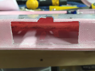
Cut out the opening for the Planearound gearbox per plans that came with it.
The opening in the cutout reveals little runs of epoxy and the parabeam fiberglass used when mating the door halves. At this point, little square reinforcement blocks are glued on either side of this opening to provide structural support.
After gluing the structural supports in place (using West 105/205 "Fast" hardener and flox), I repeated the most of this process for the other door. By the time the second door was done, the first door was done curing and I could proceed with installing the actual mechanisms. It actually wasn't too bad putting all the rods together once I had a good mental image of how it would all work.
Basically, the process is this (borrowing methods from Ed's video, Planearound's plans, and Van's plans, adding a bit of my own take):
- Start with all the door pin blocks removed, the Planearound gearbox screwed into place, and the door latch handle assembly removed.
- Take the aft factory door pin (the long one) and attach it to the aft end of the Planearound gear rack (the side with the small hole, teeth facing down) using a pin and safety wire.
- Using a precise 70/30 combination of black magic and wizardry, stick the pin/rack combo into the aft door opening and get the rack to slide into the Planearound gearbox, seemingly 10 feet away. Turn the Planearound gearbox shaft to pull the rack through the gearbox to the other side.
- Now, from the forward side, stick the Planearound mid-pushrod in through the latch pocket and mate it with the rack you just stuck in from the aft end. You'll be using the 3/8" peephole you drilled per the Planearound plans to see what you're doing.
- Using safety wire, stick the 3/16" Planearound pin into the mid-pushrod and gear rack, fastening the two together.
- Now, you can install the latch mechanism by first installing the lower gear rack as you screw the latch mechanism into the door (you may need to push the mid-pushrod out of the way).
- You can now turn the handle towards (and beyond) the "closed" position to feed the gear rack out into the aft portion of the door, with the mid-pushrod still out of the way.
- With the aft (lower) rack fed out from the handle gear, "clock" the handle to a point approximately 120 degrees beyond the closed position, insert the lower rack, and bring the handle back to the "closed" position.
- Now push the button and bring the handle 180 degrees to the "open" position. The attach point between the lower rack and the mid-pushrod should be visible in the handle pocket.
- Temporarily connect the lower rack and the mid-pushrod with a pin and turn the handle back to the "closed" position. The aft pushrod should operate smoothly and allow full travel into this position. If the Planearound gear rack bottoms out before reaching the closed position, you'll need to readjust.
- Now attempt to turn the handle *beyond* the "closed" position. The Planearound gear rack should bottom out and reach the end of its travel very quickly, maybe 10 degrees or so beyond closed at most. If the handle turns more than this, you need to readjust your clocking.
- Once the lower gear is clocked properly, remove the pin between the lower rack and mid-pushrod in order to turn the handle again past the "closed" position but not far enough to disengage the lower rack gear. I believe the proper position is about 70-80 degrees beyond "closed" (the lower rack won't disengage until about 120 degrees)
- Now, attach the forward door pin (the short one) to the upper gear rack, teeth facing down using a pin and safety wire.
- Insert the forward door pin/rack combo through the forward hole and feed it through into the latch pocket, engaging it into the door handle gear.
- Turn the latch to "closed" position, and then 180 degrees to the "open" position. The upper gear should just barely NOT come into contact with the elbow pocket as you reach the 180 degree mark. Turning beyond this point should begin to feel resistance as the rack starts to hit the fiberglass there.
- Reattach the lower rack and mid-pushrod.
After following these steps, I had a latch assembly working like this (keep in mind, the door pins are still WAY too long and still need to be trimmed):
RV-10 Door Latch in operation for the first time!
Finally, you can attach the exterior handle components for the Aerosport low profile handle, and sit back and have yourself a tasty beverage!
The Aerosport low-profile handle... spiffy!!!
That's it for now. We've got the R door done to this point, and the L door to the point where the reinforcement blocks were glued into place. Tomorrow's agenda: get the same thing done to the L door... hopefully now that we have the process figured out, it should go much more smoothly!


