Saturday, December 26, 2015

Doors - Latch Mechanism Install

So now that the doors have been trimmed and had their hinges attached, it's time to get started on the latch mechanism. Here's where it gets fun (and complicated). A friend of mine is just ahead of us in his RV-10 build and has just completed his latch mechanism within the past couple of weeks, and used the same combination of modifications we are using (the Planearound 180-degree latch and Aerosport low-profile handles). He's mentioned more than once that it's kind of hard to wrap your head around all the different things going on in the door, and it's a pretty time-consuming process. Installing the latch mechanism involves a slightly different set of skills than either metalworking or fiberglass work, although a bit of each is also required. In addition, we have to follow three different sets of plans simultaneously (the standard Van's plans, the Aerosport plans, and the Planearound plans) and figure out what order to do everything in. We look forward to the challenge!

To get started, I poured a big ol' day-after-Christmas cup of coffee and sat down in the office to watch Ed Kranz's video on installing the Aerosport low-profile door handles. I'd seen it once before when he originally posted it but at the time we weren't far enough along in our own build to really understand the process or how it would all go together. Now, with all the same parts in our shop ready to be put together, this video was extremely helpful in helping us understand the big picture of how everything would go. Huge shoutout and thanks to Ed (if we haven't already) for his awesome build site and especially these videos!

Ed's video on installing the Aerosport handles (with the Planearound 180 latch)

With that fresh in my mind and the coffee kicked in, I wandered out into the shop and got started. I decided to start with the doors by assembling and installing the handle mechanism, which involves reading both Aerosport and Van's plans. I tried to take a bunch of pictures, so I'll catalog our process with captions here as we go:

Laid the Aerosport strike plate into the latch pocket in the door


Match-drilled #30 and clecoed the plate to the door

Start-drilled #10 through the Aerosport delrin spacer to make marks in the pocket for drilling #12 holes

The "start-drills" just enough to make a mark, now drill these #12

Drilled #12 holes top and bottom

Reinstalled strike plate, traced holes for handle and lock mechanism, drew an "X" for the lock

Marked center of large hole using the "X" and other existing holes as a reference, drilled #30 pilot holes in the center of each

Enlarged the latch hole to fit the Aerosport handle inner ring

Removed the strike plate and enlarged the three trim ring holes to 1/4"

Enlarged the lock hole to 3/4" using a Unibit. It's possible to put lateral pressure on the unibit as necessary so that the next "step" steers the hole closer to center. Make sure you keep as much distance as possible between the hole and the two 1/4" trim ring holes nearby!

The lock fits into (but not through) the 3/4" hole in the fiberglass. The lock needs to actually pass *through* this hole, so it will be further enlarged. Trace a line around the perimeter of the lock

Lock removed, showing area that needs to be enlarged.

Hole enlarged, now lock fits through the door

Next, file out the lock hole in the striker plate to fit the lock. Note that the lock has a slightly fatter portion just under the head, the plate must be filed to fit this too.

Strike plate attached with lock installed and beauty ring set into place... looks really nice!

Accomplished same steps for L door

Assembled Door Handle Plate per plans on 45-10, except without C-1006C delrin block, since that is replaced by the Aerosport delrin block.


Assembled handle lever and slide per plans, additionally trimmed C-1007 to a total length of  2.22" per Aerosport plans. (The WD-1022 handle, not pictured, was also trimmed by removing 0.820" from its shaft per Aerosport plans).

Gear racks were cut in half to two 5" lengths, per Planearound plans

Aft door pin blocks have wider spacing and offset pin hole. Planearound block on left, Van's block on right. Each block is cut and sanded to fit in the door as required. The Van's block is installed first so that holes can be match-drilled from the stock blocks into the door per plans on page 45-12. Then, the door pin hole is enlarged to fit the Planearound block with its pin extension protruding into the door. The #12 holes in the skin are then match-drilled from the door back into the undrilled Planearound block. Finally, the #12 holes in the block (not the door) are enlarged to #10.

Forward door pin blocks have narrower spacing and pin hole centered between the mount holes. Van's block on left, Planearound block on right. Similar process as with the aft pin blocks.

Closeup of forward door pin block being held straight with respect to door edge using a ruler

Aft door pin block installed flush with aft door edge. Tip: I later realized it's much easier to use 3/16" (gold) clecos to hold the door pin blocks during installation so they can be removed much more easily when needed.


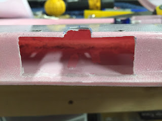
Cut out the opening for the Planearound gearbox per plans that came with it.

The opening in the cutout reveals little runs of epoxy and the parabeam fiberglass used when mating the door halves. At this point, little square reinforcement blocks are glued on either side of this opening to provide structural support.


After gluing the structural supports in place (using West 105/205 "Fast" hardener and flox), I repeated the most of this process for the other door. By the time the second door was done, the first door was done curing and I could proceed with installing the actual mechanisms. It actually wasn't too bad putting all the rods together once I had a good mental image of how it would all work.

Basically, the process is this (borrowing methods from Ed's video, Planearound's plans, and Van's plans, adding a bit of my own take):
  • Start with all the door pin blocks removed, the Planearound gearbox screwed into place, and the door latch handle assembly removed.
  • Take the aft factory door pin (the long one) and attach it to the aft end of the Planearound gear rack (the side with the small hole, teeth facing down) using a pin and safety wire.
  • Using a precise 70/30 combination of black magic and wizardry, stick the pin/rack combo into the aft door opening and get the rack to slide into the Planearound gearbox, seemingly 10 feet away. Turn the Planearound gearbox shaft to pull the rack through the gearbox to the other side.
  • Now, from the forward side, stick the Planearound mid-pushrod in through the latch pocket and mate it with the rack you just stuck in from the aft end. You'll be using the 3/8" peephole you drilled per the Planearound plans to see what you're doing.
  • Using safety wire, stick the 3/16" Planearound pin into the mid-pushrod and gear rack, fastening the two together.
  • Now, you can install the latch mechanism by first installing the lower gear rack as you screw the latch mechanism into the door (you may need to push the mid-pushrod out of the way). 
  • You can now turn the handle towards (and beyond) the "closed" position to feed the gear rack out into the aft portion of the door, with the mid-pushrod still out of the way.
  • With the aft (lower) rack fed out from the handle gear, "clock" the handle to a point approximately 120 degrees beyond the closed position, insert the lower rack, and bring the handle back to the "closed" position.
  • Now push the button and bring the handle 180 degrees to the "open" position. The attach point between the lower rack and the mid-pushrod should be visible in the handle pocket.
  • Temporarily connect the lower rack and the mid-pushrod with a pin and turn the handle back to the "closed" position. The aft pushrod should operate smoothly and allow full travel into this position. If the Planearound gear rack bottoms out before reaching the closed position, you'll need to readjust.
  • Now attempt to turn the handle *beyond* the "closed" position. The Planearound gear rack should bottom out and reach the end of its travel very quickly, maybe 10 degrees or so beyond closed at most. If the handle turns more than this, you need to readjust your clocking.
  • Once the lower gear is clocked properly, remove the pin between the lower rack and mid-pushrod in order to turn the handle again past the "closed" position but not far enough to disengage the lower rack gear. I believe the proper position is about 70-80 degrees beyond "closed" (the lower rack won't disengage until about 120 degrees)
  • Now, attach the forward door pin (the short one) to the upper gear rack, teeth facing down using a pin and safety wire.
  • Insert the forward door pin/rack combo through the forward hole and feed it through into the latch pocket, engaging it into the door handle gear.
  • Turn the latch to "closed" position, and then 180 degrees to the "open" position. The upper gear should just barely NOT come into contact with the elbow pocket as you reach the 180 degree mark. Turning beyond this point should begin to feel resistance as the rack starts to hit the fiberglass there.
  • Reattach the lower rack and mid-pushrod.

After following these steps, I had a latch assembly working like this (keep in mind, the door pins are still WAY too long and still need to be trimmed):

RV-10 Door Latch in operation for the first time!


Finally, you can attach the exterior handle components for the Aerosport low profile handle, and sit back and have yourself a tasty beverage! 
The Aerosport low-profile handle... spiffy!!!

That's it for now. We've got the R door done to this point, and the L door to the point where the reinforcement blocks were glued into place. Tomorrow's agenda: get the same thing done to the L door... hopefully now that we have the process figured out, it should go much more smoothly!

Friday, December 25, 2015

Doors Cont'd - Initial Trim and Hinge Installation

Merry Christmas! Wishing for peace and happiness to all.

Merry Christmas 2015 from Mike & Sarah-- no pic from the factory this time. And sorry about the socks... a dude's gotta stay comfy, ya know?

It's been a busy week in the factory leading up to this point! My apologies for not posting an update in a while, but rest assured things have been continuing along.

First order of business, we hit 10,000 views today on Christmas Day itself... cool! I received one email from #10,002, so I'll be in touch with that person shortly. Excited that this silly idea of ours seems to have worked!

So let's see, we left off when we had glued the two door halves together and clecoed everything to the fuselage for curing. Trimming the doors was a painstaking process, and one that is by no means complete yet. Basically, you only need to trim the doors enough so they fit flush inside the door opening, but ideally they should still be a bit "oversize" at this point. This is because until you install the hinges, window, and latch mechanisms the door won't find its final position. Once all that occurs, then you can trim the door down to its final (hopefully perfect) fit.

The first part of the initial trim is to make an "edge finder" out of two narrow strips of aluminum. The door is placed on the fuselage, and one half of the edge finder slides under the door skin, between it and the fuselage, and has a little tab on it that goes into the gap along the door opening. The other half of the edge finder has a small hole drilled in it to allow you to hold a sharpie in there while you slide the edge finder around the opening. In this way, you end up with a line drawn around the perimeter of the door that should very closely match the opening in the fuselage!

I should note that the plans have you make more use of the provided "scribe lines" visible in the outer door skin itself. However, as you'll see here, the lines are not very accurate or straight when compared to the actual cut needed. A number of builders before us have recommended not even paying attention to these lines as they are not very useful, so this is the route we took... we now see why!

Marking the L door for an initial cut (note the line drawn to leave an "ear" out for the alignment tab)

Scribe line visible here just above the blue line, quite a little ways away from (and not parallel to) the actual cut needed

Cutting the door is itself a pretty straightforward (albeit messy and time-consuming) process that basically involves cutting all the big portions away with the air cutoff tool, performing any finer-detail cuts with the dremel, and then finally sanding right down to the line using the belt sander. The real hero in this process, however, is the shop-vac. If it wasn't for the vacuum hose always being held close to our work, we'd probably have something reminiscent of the Pompeii disaster going on in our garage.

Anyway, once the cutting of both doors was completed (this took several nights' worth of work), we had two doors that fit nicely inside their openings in the fuselage.

R door nested inside of and flush with the cabin cover

Forward side of the R door - the line isn't laser-straight yet, but it doesn't have to be at this point

After this was complete, the next step is to get the door hinges installed to secure the top edge of the doors to the cabin cover. This was pretty straightforward and we followed the plans here with no real deviations. For the hinge pin, they have you cut the threads off a long AN3 bolt which seemed kind of cheesy to me, but actually worked out pretty slick. For just a touch of extra style, I put the bolt in a drill and held it to the grinder to get rid of the hex-shaped head and ended up with a much nicer-looking, rounded-head hinge pin.

After a bunch of careful drilling, countersinking, and screw installation, we had our fist glimpse of the gull-wing doors in action!

RV-10 Gull-wing doors (broomstick sold separately)

Same doors, with the optional "human broomstick" upgrade

Neato! I have to say so far, this hasn't been as difficult as I had imagined it would be. Some of the steps are a pain to be sure, but really it's not too bad as long as you can let patience prevail. We got into a rhythm of working until we got either tired or frustrated, and then just left it for another day. Sometimes this took a few hours; other times we had had enough in 30 minutes. Whatever it was though, it always seemed easy enough to pick it back up the next day and continue. I don't have an "hours-so-far" count for you, but whatever it is, I'd say it's reasonable given the work required.

So now that we have the door hinges attached, we can start on the latch mechanism... yay!


Wednesday, December 16, 2015

More Doors - Almost to 10,000 views!

Haven't posted an update this week since we got the R door glued and situated on the fuselage to cure. Really, we haven't done a whole lot more with the plane other than repeating the same steps with the L door, and then removing both doors for an initial trim.

L door glued and clamped in the same manner as the R door previously

Heat lamps set up on the L side of the plane

If I could do this over again, I might recommend increasing the number of clecos holding the door to the fuselage, especially around the most pronounced part of the curve from the side to the top. I tried to keep the same spacing as with the fuselage side skins (which is around ~4" spacing) but around the curve to the top I'd recommend more. If you look closely at the raw, untrimmed doors, they developed a slight crease at every point where the cleco held it tight, and I feel like these would be less pronounced if there were more clecos to spread the load. It shouldn't be a problem though, once the doors are trimmed to size most of the creasing will be trimmed away, and whatever remains can easily be filled. But still... something to consider.

Other than that though, We've gotten about 30-40% done with the initial trim for the R door, and the L door hasn't been trimmed at all yet. We'll get to that as time permits!

In other news, we're nearly to 10,000 views of this blog! Dunno if 10,000 hits in just under two years really counts as a "high volume" site by most standards, but we're still pretty humbled and amazed that we've come this far and have been able to share our journey with a number of folks from all over the world. Google Blogger statistics tell us that we've had visitors from not only North America but South America, Europe, Africa, Russia, China, Australia, and more! Truly awesome.

So, since December represents the "season of giving" and we feel like being a little silly, we'd like to reward the 10,000th visitor to our blog and send them something from our shop. Don't get too excited now, it's not going to be anything of too much value, but we'll try and make it meaningful in some way, and it will certainly be RV-10 related! So, if you're reading this page and the "Visitors" counter on the right says exactly 10,000, send me an email at [redacted] and let me know. If you can attach a screenshot or something that would be even better, but I realize that can be difficult at times. Honor system applies... no cheating!

Hopefully this works! If not, well, happy holidays from us both anyway... and stay tuned for more fiberglass and door work!

Sunday, December 13, 2015

Doors Continued

Continued with the doors this weekend... so far so good! Followed the procedure in the plans for preparing the door halves for joining together, and everything went pretty smoothly. I'm finding that the orbital sander connected to a vacuum cleaner makes quick work of the sanding tasks and makes little to no dust.

We did run into one snag along the way... we had decided to insulate the doors with spray foam, and our first attempt at doing this didn't go so hot. Basically, I had the idea to fill all the voids in the inner door shell (except for the areas where the door latch mechanism will go) with Great Stuff foam and then cover the exposed, wet foam with wax paper.

Covering spray foam with wax paper to help mold it into place - Don't do this!!!

The thought in my head was that if I had it all covered with wax paper, the foam would expand underneath and nicely fill any gaps, and once it cures I could just peel away the paper and magically have perfectly contoured and textured foam beneath. What really ended up happening was the foam didn't cure properly (it needs plenty of fresh air to cure, and the paper denied it that), and so it ended up as this reduced, goopy mess that stuck to the wax paper better than you would believe! It was a nasty disaster that took a while to clean up. At least I only did it to one door as a test!

We then figured out we could just spray foam the doors and let the foam expand way beyond where it needs to be, and then cut it down to size with a hacksaw blade and the orbital sander. It's pretty wasteful-- we ended up using about 2-3 cans of foam per door and cut away most of it-- but once it was done it looked pretty neat and definitely added some "substance" to the otherwise hollow and flimsy door halves.

Sarah liberally applying spray foam while the doors are clecoed to the fuselage

First pass of foam, curing in place on the fuselage

The door halves after the first pass of foam was cut and sanded down

Close up of R door, showing masked off areas for door linkage. Also, we filled some of the bigger voids (like near the lower front corner of the window) with a second pass of foam

Final pass of foam, Sarah decided to get cute with the leftover and wrote our initials in the respective doors :-) Most of it would be sanded away, but you can still barely see it...

So by this afternoon, we had both right and left doors ready to join their halves together! The next steps involved cutting some pieces of Parabeam fiberglass that was included in the finish kit. Each door needs two 5" x 9" pieces to sandwich between the door halves at the upper and lower pockets. I had never heard the stuff before, basically it's a three-dimensional fiberglass weave that is about the thickness of a piece of scotch brite, and feels kind of spongy. Each 5" x 9" piece absorbed about two pumps' worth of West System epoxy!

The four cut pieces of Parabeam fiberglass weave, two for each door

So with the fuselage door openings masked off, and everything prepared and ready to attach, it was time to mix up some epoxy. We mixed three kinds, measuring in West System dispensing pumps as a unit of measure: (1) a total of 4 pumps' worth "neat" epoxy for the two Parabeam pieces; (2) a total of 4 pumps' worth of micro slurry to slather over the exposed spray foam; and (3) a total of 10 pumps' worth of Cab-O-Sil/Flox mixture to spread around the window and outer perimeters. The Cab-O-Sil/Flox mixture was made to about a "thick oatmeal" consistency, where if you held the cup sideways for a while it would just start to pour, but just barely. Sarah and I established a system where I'd mix up batches of epoxy and stir in the necessary additives, and she'd slather it on to whatever it needed. In this way, it only took us about 15-20 minutes from the mixing of the first epoxy batch to the time we clecoed the door to the fuselage.

R door clecoed (and clamped) to the fuselage

Set up two 250W heat lamps to keep the door warm during curing

We thought about starting on the L door, but we were using all of our spring clamps and heat lamps on the one side. We'll do the other side tomorrow!


Thursday, December 10, 2015

Begin Doors

Ahh, the dreaded doors. I haven't met many folks who've said they enjoyed building the doors of their RV-10. Apparently the plans aren't the greatest, the scribe lines aren't very useful, and the parts themselves need a good amount of effort to make everything work properly. We do have the benefit, however, of following in the footsteps of many before us who documented what they did (or should have done) to make things easier during this process. Hopefully, that will help bigtime. So, here we go...

Wait... why aren't we continuing with the overhead console? Well, partially for a reason, and partially because why the heck not? The reason is that we want to do as much drilling and cutting as we can to the cabin cover before fabricating the overhead console, so we have a better understanding of what's going to go where and how all the parts fit together (hinges, strut, etc). Also, I wanted to take some more time to get even more experience with fiberglass, and I'll probably make one or two little things here and there as side-projects in order to become more familiar with the process. This isn't something a person can learn overnight!

In the meantime, I also built a crude "oven" (it's more of a "warmer" really) for our assortment of West System Epoxy. It turns out that epoxy is very temperature-sensitive and works best when just above normal room temperatures, like in the 80F-90F range. Especially as we head into the winter months here, the garage is going to be at the "bare-minimum" epoxy curing temperatures of 65-70 degrees, so the warmer the epoxy is, the better. I got the idea to make the oven originally from reading Rutan's Moldless Composite Sandwich Aircraft Construction manual, which is a highly recommended book geared towards builders of the many fabulous composite Rutan aircraft (Long-EZ, Cozy, etc), but is also very helpful for us rivet-bangers when it comes time to make fairings or custom bits for our RV's. Then, I saw one of these ovens for the first time in real life at my friend Chad's place the other day and thought, man, I gotta have one of these! So, I built one:

The EZ-Bake Oven (pun intended)

Oven from the outside, with other fiberglass-related goodies assorted all around

The oven is made from 100% genuine recycled Mikey J Scrap Material and is by no means the strongest or prettiest thing in the garage, but it came out just fine, works great, and I'm happy with it. It measures 24"L x 16"H x 16"D and is made of 1/4" plywood (thicker would have been better), some 2x2's at the corners, and 2x4's reinforcing the door. It was then lined with 1/2" insulation board, and all the cracks filled liberally with Great Stuff spray foam. The heater element is a standard 100W light bulb, and the thermostat is a Honeywell CT-410B line voltage thermostat. There's also a cheapie thermometer in there to ensure everything is working properly. The thermostat was an interesting piece, it is only rated to go up to 85 degrees F, but I was able to modify it to go higher. It turns out that all you have to do is pop the knob off the front of it, and the remaining part of the shaft will turn farther than the 85 degree stop, and will heat to at least 95 degrees or better (that's as high as I tried, but there was still more to go on the dial). Awesome! Now all of our epoxy-- except for the 205 "Fast" hardener-- is stored and incubating at around 80 degrees... we'll go higher if/as needed.

Now, on to the doors. We're going to start with the right door, and hopefully get to the point where the two halves are glued together, and then repeat with the left door. First thing to do is draw a couple lines around the window openings, and trim away the excess. Note: the plans aren't very clear about what exactly to trim, and the referenced figures show large crosshatched areas filled in around the door openings. Typically, this crosshatching in the plans means "cut this part away" although that is NOT the case here! Not very much trimming is needed at this time at all, just the middle of the window leaving a ~1-3/4" perimeter is fine. To draw the lines, I made a little "tab" out of scrap aluminum and drilled holes at the 3/4" mark and the 1-1/4" mark.

Measuring tab to aid in drawing spacing lines

3/4" and 1-1/4" lines drawn around the window opening. Another 1-3/4" line was drawn later and rough cuts were made along that line.

So far so good! Next we drilled a few index holes and sanded the inside surfaces (referred to as the "bag" side of the parts) where they will mate. The idea is to glue the door halves to each other while they are still oversize and can be laid over and clamped to the side of the fuselage. This way, the doors will match the contour of the fuselage exactly, and can then be trimmed to perfectly fit inside the door opening. Before long, we had the assembly clecoed to the side of the plane using the two index holes!

R Door laid over the cabin top for the first time, and a happy Sarah!

R Door from the inside

Neat! Next, we match-drilled a number of additional holes around the perimeter of the door. The holes along the bottom third of the door (that overlap the metal side skins) required use of a hole finder to match-drill into the holes previously left un-riveted in Section 29. I had always wondered why they had us leave those holes open... now I get it!

#40 Hole finder being used to match-drill the open holes in the side skins

Then, we departed from the plans and joined with several other folks who had a pretty smart idea to match-drill clecos just like this all the way around the rest of the door to hold it just perfect in place and shape. The holes will be easily filled later with some micro or flox, and if all goes well you'll never be able to tell we drilled a bunch of holes all around the door openings.

R Door match-drilled to fuselage

Close-up of upper aft side of door, formed perfectly to the cabin top

This is kind of cool! Now, everything has to come back apart and we have a few more steps to complete before epoxying the two halves together for good! I think I want to run a small conduit down the inside, as well as shoot some Great Stuff insulation into all the voids. We'll get to this hopefully this weekend!