Thursday, February 4, 2016

Engine Update - More Fiberglass

So I've been pretty consistently lazy with updating the blog lately, sorry about that. I guess it isn't as fun spending days and days doing layups, sanding, filling, sanding, filling, doing more layups, sanding, filling, then throwing the whole thing away and starting over.... haha. But we're learning. There just isn't that much that's happened yet that makes for an interesting blog post, which I feel is somewhat in contrast to the progress we sometimes make following along in the plans and completing all the steps in order. I feel like I haven't even looked at the plans at all in at least a month now!

Before I get to the fiberglass, a quick note on the engine. I believe I've mentioned in the past that one of the parts of this build that I was excited about the most was overhauling/building the engine myself. Being a "car guy" and having overhauled many car engines in the past, I was very excited about the prospect of doing the same on the RV-10. However, as time has gone on and we've made it this far, a thought started to occur to me that maybe it would be a better idea to let the pros handle this. I mean after all, with all the time, money, blood, sweat and yes tears put into this project so far, why put the whole project in jeopardy by attempting to do the engine myself? Although these Lycoming engines are quite simple in design, anyone familiar with them will tell you there are a surprising number of gotchas and tricks-of-the-trade that only the professionals who do this every day really know how to handle.

And even the pros have trouble sometimes! I became familiar with a situation not too long ago involving a locally-owned airplane having some engine trouble at an airport a few hundred miles away. Luckily the pilot fought the urge to "get home and check it out" and decided to stay on the ground, quickly realizing that the engine actually had a major issue, requiring a complete and immediate overhaul. The engine was a mid-time Lycoming that had been previously overhauled by a top-notch and very experienced mechanic. I personally saw the look of disappointment and confusion on his face when he heard the news. It's very likely that the problem had nothing to do directly with the quality of work that he performed, but even so, his look and attitude towards that situation certainly left an impression.

I tell that story because that was sort of the beginning of the end for me with respect to building the engine myself. The more I thought about it, the more I became certain that this was a task best handed off to someone more experienced and capable. So, I called around to a few places and have made plans to bring my setup to Poplar Grove Airmotive in Poplar Grove, IL. They are a well-respected engine overhaul shop and come highly recommended by several pilot friends who have used their engine overhaul services. They quoted me what seems to be a fair price for engine assembly and dyno testing, and hopefully what I get back from them will be a zero-time, fully airworthy and reliable engine ready to perform for us.

So in preparation for sending the engine into their shop, I've placed a few orders for the parts I still need to make this engine complete. These include bearings, gaskets, hoses, nuts and bolts, as well as some additional components. Some of the bigger-ticket items include the starter and two B&C alternators (BC460-H and BC462-3H), as well as overhauling the fuel servo, fuel pump and flow divider by Airflow Performance. Hopefully, I'll have a complete stack of parts ready to go by the end of the month, and I can haul it all over to IL to get that process started!

In the meantime, we're continuing with our work on fiberglass. I started making the center console/quadrant/armrest, and tried to take a few pictures along the way:

NOTE: It will be painfully obvious that the design of this console is "inspired" by the new Aerosport "Quad Console" armrest... it can probably best be described as a poor-man's homemade version of it. Hopefully it will be just as functional and just nearly as pretty when complete!

Spent many DAYS making a foam "plug" that will be used to make the center console.

Random photo of the adhesive being used to bond the foam: Glidden Gripper primer! I found this trick from watching a youtube video where several different adhesives were used for comparison. Many traditional adhesives will actually melt the foam and can't be used, leaving few alternatives that actually make a good bond... this stuff works great, and cleanup is painless!
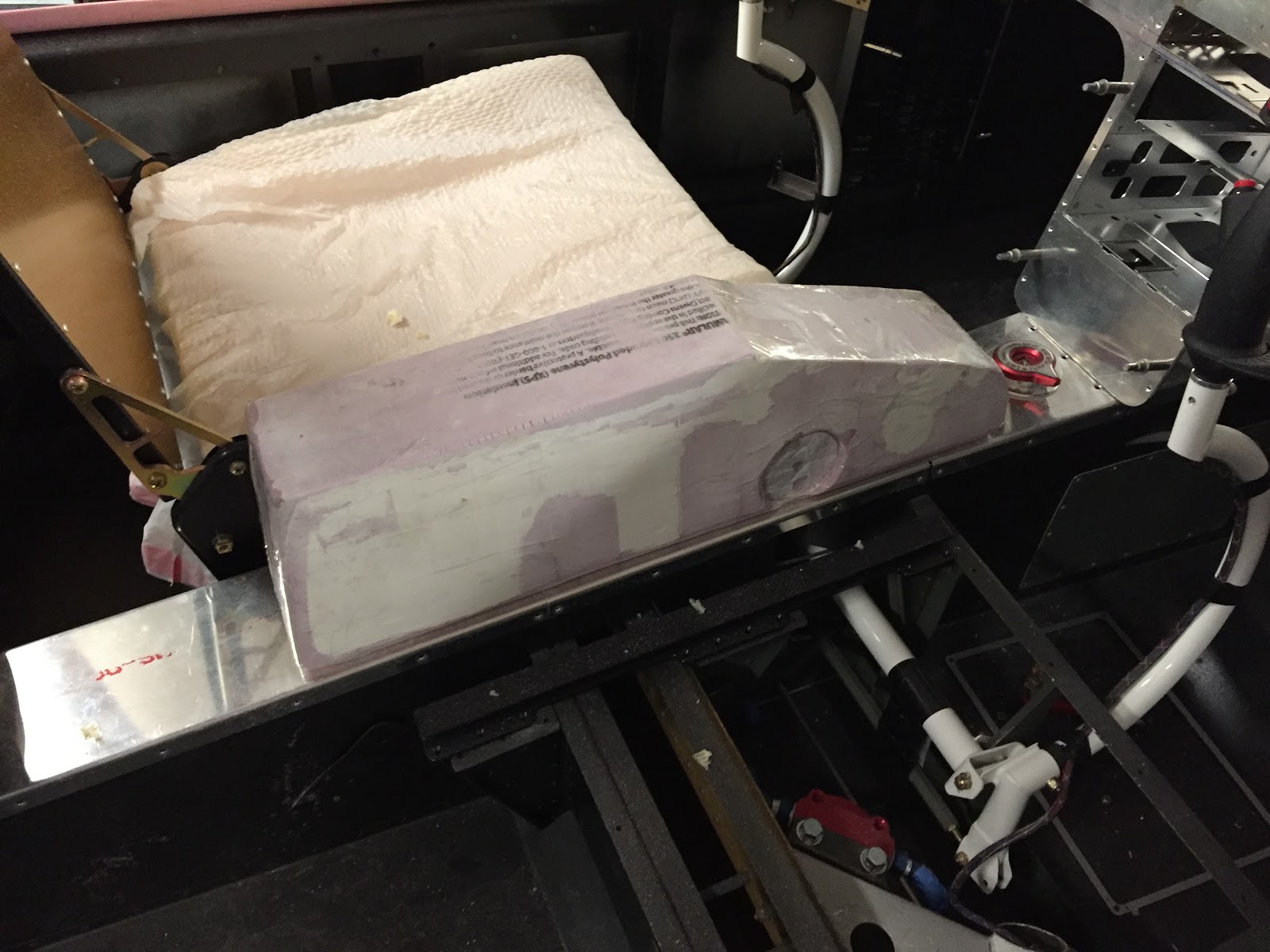

Approximate location on the tunnel. The throttle quadrant will be in the slanted forward part, and there will be a padded armrest cover that opens into a storage box (big enough to hold a sectional chart!) inside the main area.


After layups and initial trim: The console is made in two separate halves, one slightly overlapping the other, so that they can be removed from the plug and then bonded together as a hollow piece.

The first few clecos being installed to clamp it together for bonding

Since these photos were taken, the console has been bonded together, sanded, filled, and then cutouts have been made in the top, front and back for various panels and openings. It's coming together, but man this isn't something that can just be built in a day.

Other parts coming along are the "A-pillars" in the cabin cover, which I've successfully run conduit through and sealed in place with spray foam. I shaped the foam to approximate what I wanted and then put a single layup over it. This has resulted in an EXTREMELY wavy base layer, on top of which I will need to fill and sand everything to become smooth and properly contoured. I'll try and post some photos of that endeavor next time.

We have some plans coming up over the next week or two, so I wouldn't count on much work getting done on the plane until maybe after Valentine's day or so... but I will keep trying to find some time to post updates!


Tuesday, January 26, 2016

Fiberglass, and a new toy on the way!

It feels like we're almost at a standstill on the fiberglassing front. Just working on the general shape and layout of the overhead console and the center console throttle quadrant/armrest/storage compartment. It's hard to take pictures of stuff when your hands are covered in epoxy and making a giant mess!

I'm getting "better" at fiberglassing techniques. I wouldn't say I'm "good" yet by any means... but with lots of practice and time spent, it's getting there. I'll try and post some pictures of the parts as they are coming together soon.

I also broke out the sewing machine (an old hand-me-down Husqvarna Viking 6000-series) and started to sew some practice seat covers from some cheap vinyl I had bought at the local fabric store. The stuff costs like $5/yd on clearance, so it's perfect to mess up on and make all the mistakes before we get our $65/yd Ultraleather. I made some simple patterns for the backseat and got to work, and the results turned out better than I had imagined-- comfy and nice-looking, at least for a total beginner!

Unfortunately, the sewing machine itself isn't going to cut it. The reverse drive is broken, and the needle doesn't sew on center; in fact it wanders back and forth a bit as you sew. Looking online, this is a common issue for this model of machine, and opening it up, I noticed a number of cams and gears that were shedding plastic and binding in ways they shouldn't be. It's pretty hard to complain though, since we got the machine for free from a friend, but this isn't going to be acceptable for the seats. So, after a brief discussion Sarah and I decided to splurge for a new Sailrite Ultrafeed LSZ-1 machine. Here's a promo video of it:


Hopefully, with that machine we can really get started making some interior pieces. Excited for that!

Stay tuned for more fiberglass and interior work!

Tuesday, January 19, 2016

Odds & Ends

So it's been a while since the last update. Things are going well, but slowly. We've been working on sanding the inside of the cabin cover, installing conduit along the front "A-pillars" and "B-pillars", and filling in the voids with spray foam to then cover with fiberglass. I'm also trying to come up with the desired shape for the overhead switch panel, which will contain all my lights and dimming controls. I received my switch and terminal order from Digikey the other day, so I took a piece of scrap aluminum and quickly made a (very) rough mockup of what I had envisioned for the switch panel:

Overhead switch panel, v0.0.1

It came out "okay"... I think there needs to be a bit more room vertically between the dimmers and the switches, and also maybe just a smidge more space between each toggle, although I can live with it as-is. The idea will also be to have both the upper and lower edges of the panel curved, to better fit in the given space and give it kind of a more elegant look. At least that's what I'm going for-- it may very well end up looking like some kind of super-cheesy clown smile instead. We'll see.

I need to figure out how to illuminate these too. Right now the thought is to make a piece of clear acrylic that is painted a solid opaque color, and is then etched to allow light to pass through for all the legends and graphics. Another option would be to get a panel made from a place like engravers.net and backlight them with LED's. Although I like that idea (and I've seen some really sweet-looking panels made this way), I'd like to first try the acrylic method and see how far I can get. This will be on a growing list of back-burner projects that I'll get to, eventually.

Continuing on the electrical side of things, I also received my order for 12V accessory plugs. I kind of "splurged" on this and went with the VW/Audi parts that I've seen discussed on the forums. They're pretty slick-looking-- they have a spring-loaded door with "12V" marked on the front, and should provide a nice finishing touch to the interior when it all comes together. I'd take a picture, but one of the parts I received was incorrect and I'll need to exchange that out before I can move forward on this. There will be a total of three outlets in the plane: one for each of the two front passengers, and a third in the middle for the back seat.

I'm also working on preparations for the avionics. Specifically, I'm drafting all of my own wiring diagrams for the plane using the program Kicad, an open-source schematic capture and PCB layout program I've used for quite some time on a number of different projects. This is of course BY FAR the biggest of those projects, and it's going to take many weeks (if not months) to finalize a wiring diagram before I can actually cut, strip and crimp my first wire. The diagram will be comprehensive in nature and cover all of the avionics interconnects (of which there are many hundreds) as well as ship's wiring for things like lights, trim, flaps, etc etc. It's a fun task (yes, I actually enjoy this stuff) but it's also very tedious and does take a long time. It also has a tendency to make me cross-eyed after a few hours of reading through the thousands of PDF pages of install manuals and datasheets, trying to figure everything out. I'm getting there, slowly but surely!

Alright, I've talked enough. Here's a few pictures of many of the other accomplishments made this last week:

Rigged up the GSA28 pitch servo, and installed the optional Van's RV-10 ADAHRS tray to hold another GSA28 servo for the yaw damper. Fabricated a bracket to hold the yaw damper bellcrank, centered behind the elevator bellcrank. I'll probably re-make the ADAHRS tray itself out of thicker material and extend it forward slightly so I can also mount my GDL39R ADSB box. I also re-made the yaw damper arm into a more "boomerang" shape that has slightly different geometry that will work better with the movement of the rudder cables. I'll make a full post about the yaw damper and all the parts used to construct it once it's finalized.

Installed the Tosten stick grips... yay! I may cut another bit off the sticks to bring them down just a tad more. I started with them in a little high because... well... you can always cut more off but it's real hard to make them taller again!


Lastly, a quick montage of cutting out the rear NACA vent holes. Thanks to my friend Derek for stopping over and taking some of the action shots :-)
Traced the front NACA hole onto a piece of Lean Pockets cardboard, cut it out, and then traced it on this location in the aft fuselage skin. The vertical line shown is 10" back from (and parallel to) the seam between the mid fuse side skin and the tailcone, with a centerline drawn between the two rivet lines.


Me getting started with the cut using a Dremel tool

Cut almost done...

After a bit of filing, it looks great! Just the same as the holes in the front... woo!

That's it for now... until next time!


Monday, January 11, 2016

Overhead Console - Panel

Quick update today... got some decent work in over the weekend but really doesn't feel like much has changed. I guess a lot has been accomplished, but nothing can really be checked off yet, and it feels like everything is in a half-completed state (I'm finding this seems to happen periodically). Also, I'm really finding out what a specialized skill fiberglassing is. People who are good at it make it look so darn easy, and there are plenty of beautiful examples that can be found online of parts people made for their airplanes from fiberglass... I wouldn't say mine fall into that category yet. The good news, though, is I feel like I'm learning a lot, and eventually I'll be able to make the parts I need for this project.

I was able to re-make the ducting system for the overhead console, using a slightly modified design and an improved method of actually laying the glass. It came out much better this time, but it certainly still has its flaws. The good news is, of course, these parts aren't structural in any way, so as long as they don't fall off the ceiling in flight or something, I think we're ok from a safety standpoint.

Version 2.0 of the overhead ducting system

It's pretty similar in theory to the first one-- the duct on the left side brings air to the front two vents, and the duct on the right side brings air to the rear two vents. There will be a pair of servos in the tailcone controlling flow to each of these two ducts, and in this way we can control the amount of fresh air going to the front and back.

Now, the idea is to cover these ducts with the actual console itself. Since these ducts will be mostly hidden beneath the console, I'm not too terribly worried about how perfect they look, as long as they are airtight and have a good bond to the cabin cover. If all works out like what's in my mind, the final product will be a seamless-looking console that has four vents, four spotlights, some access panels, and some recessed accent lights to serve as dome and cargo lighting. Oh yeah, and the switch pod. Still at square one for that... also need to build a center console for the armrest and throttle quadrant. Sheesh! Lots more fiberglass to do.

In between epoxy curing sessions, I also started work on the panel. I had previously purchased a 24" x 48" sheet of 0.070" aluminum from Aircraft Spruce and intended to cut out my own (slightly larger) version of the instrument panel Van's gives you. I began by tracing out the original instrument panel and marking all the attach holes that go along the upper edge. Then, I drew a straight line across the bottom that is about a half inch below where the standard switch bar ends, thus making the panel about a half inch taller than stock, and all in one sheet. Lastly, I drew in lines for the center console and side vents and began cutting everything out. I used a combination of a jigsaw, dremel, belt sander, and an array of files:

New instrument panel after initial cut

Looks good! I sat down in the left seat and discovered there was still plenty of room for my knees too. The extra half inch of height really isn't noticeable at all from a comfort side of things, but it totally gives the appearance of having WAY more panel space...cool!

So now comes the fun part: laying out where all the instruments are going to go. I've agonized over this for months now... so many options, each with their advantage and disadvantage. It's time to make my mind up and just go for it. If I end up hating the layout, I guess I can always try again. Hopefully that won't happen.

The basic idea for the panel layout is to have the 10" G3X touch screens centered for each pilot/copilot, and the Mini-X backup EFIS in the center. The GTN750 and GMA350c audio panel will be mounted into the console (a bit low compared to many other configurations, more on this later), and the GMC307 flight control panel will be mounted high and center. This layout seemed to work the best so that the aircraft can be piloted just as easily form the left seat as the right seat-- one of our main requirements. So, I did some more measuring, tracing, and cutting, and ended up with this for a panel:

Instrument panel after cutouts for avionics

Good stuff! I found it wasn't nearly as hard to cut it out as I was thinking it might be. The hardest part was drawing all the lines to be perfectly straight and square. If you look super close there are a few cut lines that aren't perfect, but the mounting of all the instruments covers it all up nicely. So far so good... now it's on to switches!

I'm struggling a bit with the layout of the switches, but I think I have a general idea of where things are going to go. I'll post a diagram at some point when I finalize the layout, but right now I'm at the point of figuring out exactly what model I need for every single switch, indicator, and potentiometer. Kind of a fun task, but very tedious too. Also, turns out quality switches aren't the cheapest thing in the world. I'll be placing a pretty hefty order with Digikey in the coming days that should cover most of our immediate needs for switches and the like, then we will go from there.

That's it for now! Next up, more work on the overhead and panel...


Tuesday, January 5, 2016

Air Trip!!!

Well, I've been waiting for some decent weather to fly up to Farmington, MN (on the outskirts of Minneapolis) to pay a visit to Stein Air to pick up my avionics order in person. Of course, visiting in person wasn't explicitly required for any reason, but it actually worked out to be the same--or even slightly lesser--cost to fly up there myself instead of having all the stuff shipped to me. Plus, it was a great excuse to fly, and I wanted to meet and shake hands with the folks I'd been dealing with!

The only problem we had was that it seemed as though the weather was continually conspiring against us for the last 2-3 weeks in a row, keeping us from making it up there. Although I do have an instrument rating, the Archer we currently fly isn't really cut out for it. Plus, most days the weather wasn't even good enough to fly IFR in a small plane... freezing fog, ice, snow, gusty winds... all the stuff we pilots have nightmares about. Better to be on the ground wishing we were up in the sky rather than the other way around, right?

Anyway, today we FINALLY got some good weather to make the relatively short ~1hr trip up there. Unfortunately Sarah was stuck at work, but I was able to enlist my friend Derek to tag along and keep me company on the journey. So, we hopped in "Julie" the Archer and blasted off to the north!

Negotiating through the outermost rings of the Minneapolis Class B airspace and landing at Airlake Airport (KLVN) proved to be very straightforward and made for an easy flight. Upon landing, I gave Stein a call and Jed picked us up in Stein's really nice BMW SUV... I'm not used to fancy vehicles like that! We had a great visit, but like a doofus I forgot to take any pics while we were there. We got the "nickel tour" and met most of the employees, who were all hard at work wiring up avionics, making harnesses, cutting panels on the CNC mill, and drafting schematic diagrams on a giant computer monitor. Jed even showed us their new laser etching machine that they apparently just started using within the last month or two. Neat! It was definitely a clean, well-organized facility, and everyone was clearly hard at work doing "real stuff" putting something together for an assuredly happy customer somewhere around the world. They were all happy to take a minute out of their day though to say hello and show us what they were up to. It was really cool... I felt fortunate that we live close enough to have been able to make the trip up feasible... if you ever have the opportunity to visit, I definitely recommend it!

!!!Thanks again to Jed, Stein, and all the other employees at Stein Air for a great visit!!!

With that, and a short ride in the Beemer back to the airport, we carefully packed up our mother load of boxes into the Archer and blasted off to the south. As the sun started to set, I had to snap a couple photos:

Southbound from the Minneapolis area

Crossing from Minnesota into Iowa - pretty rural, but still a very serene beauty.

Passing over New Hampton, IA... this town looked almost "fake" from the air because it was so pretty with the sunset!

Touching down at KIIB, we drove back to Marion, dropped Derek off and finally got home. Sarah was eagerly awaiting my return with "the goods," and after a quick unloading and sorting session we had an intimidating pile of avionics to go through!

N165MJ avionics (with a few goodies from Stein) after unloading and sorting... love the red "We're not happy 'til you're broke" keychains in the middle! A dose of reality... ouch.

Had to unbox the GTN-750 and one of the G3X Touch displays to have a look... it's like Christmas :-)

Anyway, with all that it's time to finish up some things at work and then call it a night... coming soon, more work on the overhead console!


Sunday, January 3, 2016

Happy 2016!

Man, it feels like I haven't posted an update since LAST YEAR. <groan>

Well, we've made some forward progress, but not really anything too terribly note- or photo-worthy. Additionally, I've been working on a side-project in the garage, swapping a transmission out of my old '77 Impala for one that has an overdrive in it (TH200 for a TH200-4R for all you gearheads). It's kind of tough doing a tranny swap working around all the airplane parts that are in the way, but hey that's life I suppose. It's almost done now, just have to figure out the necessary modifications to the crossmember. Anyway, as for work on the plane itself, the doors and cabin cover have come back off, and this allowed us to tie off a number of loose ends that remained on the fuselage itself. Namely:

  • Completed securing, attaching, and tightening all of the fuel system components. Now the only part of the fuel system that remains are the connections to/from the tanks and of course FWF.
  • Completed assembly of the control system, including measuring the pushrod lengths for the elevator controls and safety-wiring the appropriate rod ends. Fabricated a small "washer joust" out of 0.032" aluminum, drilling a 7/16" hole at the end, and then sanding the end off until only half the hole remains. This way you can push washers in between the different control system components as necessary without fumbling around with your hands.
  • Attached nutplates along the mid fuse longerons by the rear seat area. This was a leftover task from the "access covers" section because I had experienced significant difficulty setting rivets in this area. They are at kind of a funny angle and I didn't have anything that seemed to work to buck these. Ultimately, I was able to succeed using a swivel flush set and an array of different bucking bars.
  • Swapped out all the hardware attaching the rear seat belt anchors in the tailcone with stainless bolts and custom stainless cables. This is a recommended procedure for any ferrous metal located within about 3 feet of the magnetometer, per Garmin's instructions. I had previously attempted to do this, but had a terrible experience with galling and broke a number of bolts. I was able to succeed this time by lubricating the bolts first.
  • Installed a few of the access covers and began test-fitting some of the Aerosport interior panels that I have. It's cool to get a glimpse of what the interior is going to look like!
So basically, the fuselage is getting pretty darn close to "done" status. Items still on the "to-do" list include rudder pedals (still holding out for some Control Approach pedals... it's not the funnest waiting game in the world but I figure as long as I have other stuff to work on we'll keep dragging it out) and dimpling/riveting the upper forward fuselage, which I'm going to lump in with work on the panel. Hopefully, we'll be able to get started on the panel sometime soon too! Still need to make it up to the Minneapolis area to pick up my avionics from Stein. Of course we can have them ship all the stuff but I thought it would be fun to get up there in person and pick it up (cost would be about the same or even a little cheaper than shipping with insurance). It seems like the weather has been conspiring against us making a flight up there for literally weeks now! We may have to just break down and drive up there. Maybe as a test drive in the Impala once the tranny swap is done... hmmmm.

Other than that, the work that remains now is to finish up the cabin cover, which mostly involves fabricating the overhead console, and get it final-installed on the fuselage. After that happens, we can finish with the doors, and then we can proceed with the rest of the finish kit items. Stay tuned for all that!

Saturday, December 26, 2015

Doors - Latch Mechanism Install

So now that the doors have been trimmed and had their hinges attached, it's time to get started on the latch mechanism. Here's where it gets fun (and complicated). A friend of mine is just ahead of us in his RV-10 build and has just completed his latch mechanism within the past couple of weeks, and used the same combination of modifications we are using (the Planearound 180-degree latch and Aerosport low-profile handles). He's mentioned more than once that it's kind of hard to wrap your head around all the different things going on in the door, and it's a pretty time-consuming process. Installing the latch mechanism involves a slightly different set of skills than either metalworking or fiberglass work, although a bit of each is also required. In addition, we have to follow three different sets of plans simultaneously (the standard Van's plans, the Aerosport plans, and the Planearound plans) and figure out what order to do everything in. We look forward to the challenge!

To get started, I poured a big ol' day-after-Christmas cup of coffee and sat down in the office to watch Ed Kranz's video on installing the Aerosport low-profile door handles. I'd seen it once before when he originally posted it but at the time we weren't far enough along in our own build to really understand the process or how it would all go together. Now, with all the same parts in our shop ready to be put together, this video was extremely helpful in helping us understand the big picture of how everything would go. Huge shoutout and thanks to Ed (if we haven't already) for his awesome build site and especially these videos!

Ed's video on installing the Aerosport handles (with the Planearound 180 latch)

With that fresh in my mind and the coffee kicked in, I wandered out into the shop and got started. I decided to start with the doors by assembling and installing the handle mechanism, which involves reading both Aerosport and Van's plans. I tried to take a bunch of pictures, so I'll catalog our process with captions here as we go:

Laid the Aerosport strike plate into the latch pocket in the door


Match-drilled #30 and clecoed the plate to the door

Start-drilled #10 through the Aerosport delrin spacer to make marks in the pocket for drilling #12 holes

The "start-drills" just enough to make a mark, now drill these #12

Drilled #12 holes top and bottom

Reinstalled strike plate, traced holes for handle and lock mechanism, drew an "X" for the lock

Marked center of large hole using the "X" and other existing holes as a reference, drilled #30 pilot holes in the center of each

Enlarged the latch hole to fit the Aerosport handle inner ring

Removed the strike plate and enlarged the three trim ring holes to 1/4"

Enlarged the lock hole to 3/4" using a Unibit. It's possible to put lateral pressure on the unibit as necessary so that the next "step" steers the hole closer to center. Make sure you keep as much distance as possible between the hole and the two 1/4" trim ring holes nearby!

The lock fits into (but not through) the 3/4" hole in the fiberglass. The lock needs to actually pass *through* this hole, so it will be further enlarged. Trace a line around the perimeter of the lock

Lock removed, showing area that needs to be enlarged.

Hole enlarged, now lock fits through the door

Next, file out the lock hole in the striker plate to fit the lock. Note that the lock has a slightly fatter portion just under the head, the plate must be filed to fit this too.

Strike plate attached with lock installed and beauty ring set into place... looks really nice!

Accomplished same steps for L door

Assembled Door Handle Plate per plans on 45-10, except without C-1006C delrin block, since that is replaced by the Aerosport delrin block.


Assembled handle lever and slide per plans, additionally trimmed C-1007 to a total length of  2.22" per Aerosport plans. (The WD-1022 handle, not pictured, was also trimmed by removing 0.820" from its shaft per Aerosport plans).

Gear racks were cut in half to two 5" lengths, per Planearound plans

Aft door pin blocks have wider spacing and offset pin hole. Planearound block on left, Van's block on right. Each block is cut and sanded to fit in the door as required. The Van's block is installed first so that holes can be match-drilled from the stock blocks into the door per plans on page 45-12. Then, the door pin hole is enlarged to fit the Planearound block with its pin extension protruding into the door. The #12 holes in the skin are then match-drilled from the door back into the undrilled Planearound block. Finally, the #12 holes in the block (not the door) are enlarged to #10.

Forward door pin blocks have narrower spacing and pin hole centered between the mount holes. Van's block on left, Planearound block on right. Similar process as with the aft pin blocks.

Closeup of forward door pin block being held straight with respect to door edge using a ruler

Aft door pin block installed flush with aft door edge. Tip: I later realized it's much easier to use 3/16" (gold) clecos to hold the door pin blocks during installation so they can be removed much more easily when needed.


Cut out the opening for the Planearound gearbox per plans that came with it.

The opening in the cutout reveals little runs of epoxy and the parabeam fiberglass used when mating the door halves. At this point, little square reinforcement blocks are glued on either side of this opening to provide structural support.


After gluing the structural supports in place (using West 105/205 "Fast" hardener and flox), I repeated the most of this process for the other door. By the time the second door was done, the first door was done curing and I could proceed with installing the actual mechanisms. It actually wasn't too bad putting all the rods together once I had a good mental image of how it would all work.

Basically, the process is this (borrowing methods from Ed's video, Planearound's plans, and Van's plans, adding a bit of my own take):
  • Start with all the door pin blocks removed, the Planearound gearbox screwed into place, and the door latch handle assembly removed.
  • Take the aft factory door pin (the long one) and attach it to the aft end of the Planearound gear rack (the side with the small hole, teeth facing down) using a pin and safety wire.
  • Using a precise 70/30 combination of black magic and wizardry, stick the pin/rack combo into the aft door opening and get the rack to slide into the Planearound gearbox, seemingly 10 feet away. Turn the Planearound gearbox shaft to pull the rack through the gearbox to the other side.
  • Now, from the forward side, stick the Planearound mid-pushrod in through the latch pocket and mate it with the rack you just stuck in from the aft end. You'll be using the 3/8" peephole you drilled per the Planearound plans to see what you're doing.
  • Using safety wire, stick the 3/16" Planearound pin into the mid-pushrod and gear rack, fastening the two together.
  • Now, you can install the latch mechanism by first installing the lower gear rack as you screw the latch mechanism into the door (you may need to push the mid-pushrod out of the way). 
  • You can now turn the handle towards (and beyond) the "closed" position to feed the gear rack out into the aft portion of the door, with the mid-pushrod still out of the way.
  • With the aft (lower) rack fed out from the handle gear, "clock" the handle to a point approximately 120 degrees beyond the closed position, insert the lower rack, and bring the handle back to the "closed" position.
  • Now push the button and bring the handle 180 degrees to the "open" position. The attach point between the lower rack and the mid-pushrod should be visible in the handle pocket.
  • Temporarily connect the lower rack and the mid-pushrod with a pin and turn the handle back to the "closed" position. The aft pushrod should operate smoothly and allow full travel into this position. If the Planearound gear rack bottoms out before reaching the closed position, you'll need to readjust.
  • Now attempt to turn the handle *beyond* the "closed" position. The Planearound gear rack should bottom out and reach the end of its travel very quickly, maybe 10 degrees or so beyond closed at most. If the handle turns more than this, you need to readjust your clocking.
  • Once the lower gear is clocked properly, remove the pin between the lower rack and mid-pushrod in order to turn the handle again past the "closed" position but not far enough to disengage the lower rack gear. I believe the proper position is about 70-80 degrees beyond "closed" (the lower rack won't disengage until about 120 degrees)
  • Now, attach the forward door pin (the short one) to the upper gear rack, teeth facing down using a pin and safety wire.
  • Insert the forward door pin/rack combo through the forward hole and feed it through into the latch pocket, engaging it into the door handle gear.
  • Turn the latch to "closed" position, and then 180 degrees to the "open" position. The upper gear should just barely NOT come into contact with the elbow pocket as you reach the 180 degree mark. Turning beyond this point should begin to feel resistance as the rack starts to hit the fiberglass there.
  • Reattach the lower rack and mid-pushrod.

After following these steps, I had a latch assembly working like this (keep in mind, the door pins are still WAY too long and still need to be trimmed):

RV-10 Door Latch in operation for the first time!


Finally, you can attach the exterior handle components for the Aerosport low profile handle, and sit back and have yourself a tasty beverage! 
The Aerosport low-profile handle... spiffy!!!

That's it for now. We've got the R door done to this point, and the L door to the point where the reinforcement blocks were glued into place. Tomorrow's agenda: get the same thing done to the L door... hopefully now that we have the process figured out, it should go much more smoothly!

Friday, December 25, 2015

Doors Cont'd - Initial Trim and Hinge Installation

Merry Christmas! Wishing for peace and happiness to all.

Merry Christmas 2015 from Mike & Sarah-- no pic from the factory this time. And sorry about the socks... a dude's gotta stay comfy, ya know?

It's been a busy week in the factory leading up to this point! My apologies for not posting an update in a while, but rest assured things have been continuing along.

First order of business, we hit 10,000 views today on Christmas Day itself... cool! I received one email from #10,002, so I'll be in touch with that person shortly. Excited that this silly idea of ours seems to have worked!

So let's see, we left off when we had glued the two door halves together and clecoed everything to the fuselage for curing. Trimming the doors was a painstaking process, and one that is by no means complete yet. Basically, you only need to trim the doors enough so they fit flush inside the door opening, but ideally they should still be a bit "oversize" at this point. This is because until you install the hinges, window, and latch mechanisms the door won't find its final position. Once all that occurs, then you can trim the door down to its final (hopefully perfect) fit.

The first part of the initial trim is to make an "edge finder" out of two narrow strips of aluminum. The door is placed on the fuselage, and one half of the edge finder slides under the door skin, between it and the fuselage, and has a little tab on it that goes into the gap along the door opening. The other half of the edge finder has a small hole drilled in it to allow you to hold a sharpie in there while you slide the edge finder around the opening. In this way, you end up with a line drawn around the perimeter of the door that should very closely match the opening in the fuselage!

I should note that the plans have you make more use of the provided "scribe lines" visible in the outer door skin itself. However, as you'll see here, the lines are not very accurate or straight when compared to the actual cut needed. A number of builders before us have recommended not even paying attention to these lines as they are not very useful, so this is the route we took... we now see why!

Marking the L door for an initial cut (note the line drawn to leave an "ear" out for the alignment tab)

Scribe line visible here just above the blue line, quite a little ways away from (and not parallel to) the actual cut needed

Cutting the door is itself a pretty straightforward (albeit messy and time-consuming) process that basically involves cutting all the big portions away with the air cutoff tool, performing any finer-detail cuts with the dremel, and then finally sanding right down to the line using the belt sander. The real hero in this process, however, is the shop-vac. If it wasn't for the vacuum hose always being held close to our work, we'd probably have something reminiscent of the Pompeii disaster going on in our garage.

Anyway, once the cutting of both doors was completed (this took several nights' worth of work), we had two doors that fit nicely inside their openings in the fuselage.

R door nested inside of and flush with the cabin cover

Forward side of the R door - the line isn't laser-straight yet, but it doesn't have to be at this point

After this was complete, the next step is to get the door hinges installed to secure the top edge of the doors to the cabin cover. This was pretty straightforward and we followed the plans here with no real deviations. For the hinge pin, they have you cut the threads off a long AN3 bolt which seemed kind of cheesy to me, but actually worked out pretty slick. For just a touch of extra style, I put the bolt in a drill and held it to the grinder to get rid of the hex-shaped head and ended up with a much nicer-looking, rounded-head hinge pin.

After a bunch of careful drilling, countersinking, and screw installation, we had our fist glimpse of the gull-wing doors in action!

RV-10 Gull-wing doors (broomstick sold separately)

Same doors, with the optional "human broomstick" upgrade

Neato! I have to say so far, this hasn't been as difficult as I had imagined it would be. Some of the steps are a pain to be sure, but really it's not too bad as long as you can let patience prevail. We got into a rhythm of working until we got either tired or frustrated, and then just left it for another day. Sometimes this took a few hours; other times we had had enough in 30 minutes. Whatever it was though, it always seemed easy enough to pick it back up the next day and continue. I don't have an "hours-so-far" count for you, but whatever it is, I'd say it's reasonable given the work required.

So now that we have the door hinges attached, we can start on the latch mechanism... yay!