Deburred the L wing ribs for bottom skins, and all four bottom skin wing box stiffeners. This EZ-Burr makes things about as simple as possible... still, a thousand holes is a thousand holes, and it still takes some time. It definitely isn't exactly an edge-of-your-seat kind of activity. Good news is, the ribs and stiffeners are all done now, just need to do the skins themselves.
Once that was done, we shifted back to reviewing everything left to do on the tanks. We realized we still had to attach nutplates to the Zee attach brackets. There are a total of 36 nutplates that need to be installed, which is a perfect task to bring into the living room and do while you're watching TV and sipping a tasty beverage. So, that's what we did, and where we left off for the day. Still looking like Saturday will be a good time for baffle installation... stay tuned!!
Thursday, April 30, 2015
Wednesday, April 29, 2015
Fuel Tanks
We're getting so close to being done with the tanks I can smell it! Or maybe that's just the proseal, acetone and MEK. Anyway, whatever it is we're almost done. Tonight we soldered in the connectors for the capacitive fuel sensors and rough-installed the Stewart Warner float fuel senders. Bending the float arms was a little trickier than I imagined it would be, because the floats have to clear both the upper stiffener and the vent line-- there isn't much more space there than the width of the float itself. Additionally, on the R tank, where the float attaches to the rod there is a 'barb' on the rod that could potentially catch on a rivet, sticking the float in the "up" position. This would be bad for obvious reasons, so I was forced to put an extra "Z" bend in the rod on the right side to ensure it would stay clear. The extra bend changes the geometry slightly between the up and down positions, so I may try and replicate that bend so both sides behave the exact same way. For now, here is the position and measured resistances for both floats in the full and empty positions.
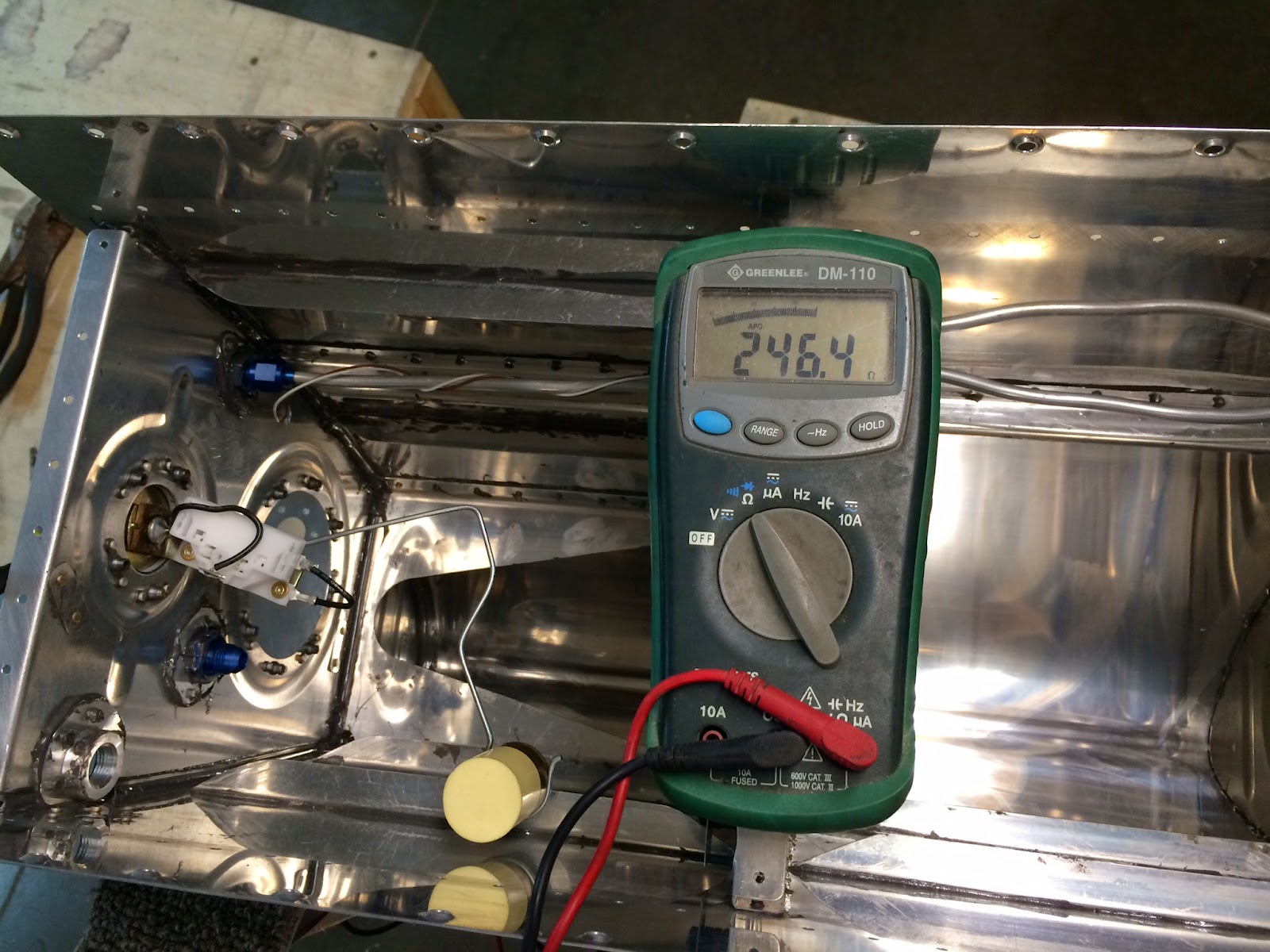


R tank empty - 246.4 ohms
R tank full - 30.4 ohms
L tank empty - 256.5 ohms See Update 5/3/2015
L tank full - 56.4 ohms See Update 5/3/2015
Seems ok to me, except the geometry in L tank (without the exta Z-bend) doesn't allow the sensor to swing all the way to the "full" position, resulting in a slightly higher resistance (56.4 ohm) than the desired 30-ohm. The R side with the extra Z-bend came out perfectly, so I'm thinking we'll be adding that same bend to the L side.
Otherwise, once that was done we got out my new favorite tool, the EZ-Burr, and started deburring the wing ribs for the bottom skins. Got all the way through the R wing!
Tomorrow we'll probably deburr the L wing and get everything ready for baffle installation... looking like Saturday will be the last day we see the inside of these tanks!
Monday, April 27, 2015
High Performance Endorsement
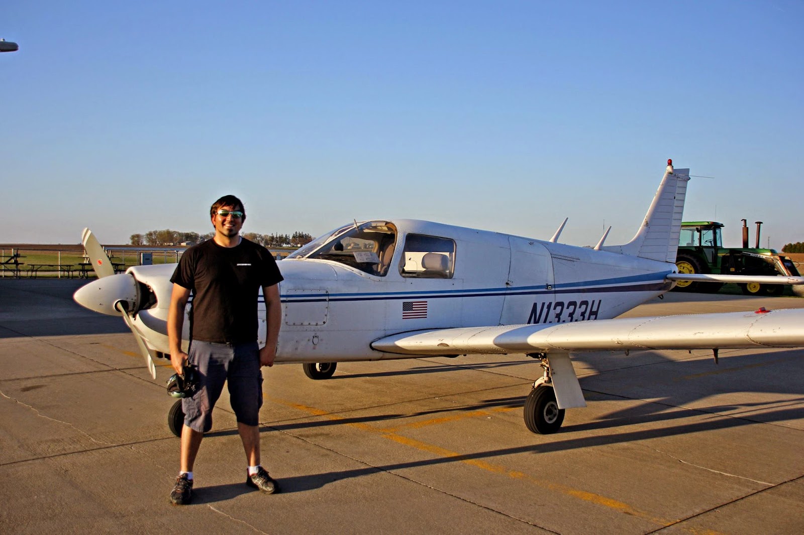
Didn't get a chance to do any building today because I got a call from my friend Jonathan who runs a local flight school, they just bought an old Piper Lance that was an ex-Ameriflight cargo hauler and will be using it for flight training. I've been searching for what feels like forever to find a high performance trainer in the area, and there simply hasn't been one! Really frustrating. Since the RV-10 is in excess of 200hp (they are typically 260hp), it is considered high performance and requires an extra endorsement to be qualified to fly it. Every rental plane around here is somewhere between 150hp-180hp with the occasional 200hp, but even those don't qualify because the plane has to be "in excess" of 200. So I've been on a mission to get the endorsement as soon as possible. Anyway I jumped at the opportunity to run over there after work and knock out the endorsement in this 300hp beast of an airplane. It flew like a Cherokee on steroids, but really wasn't all too difficult to adjust to. The lesson went really well, and it was super fun to be back in the air with one of my favorite instructors... it had been a while. Looking at speeds and fuel flows, I couldn't help but crack a smile knowing that our RV-10 will go faster, AND on less fuel. Love it!
I had such a good time, and it was such a beautiful evening for flying, we decided to hop in their 7GCAA Citabria to do some pattern work afterwards. Flying tailwheel aircraft is a guilty pleasure for me-- it's really challenging and I'm not that good at it yet, but every time I fly one I think I get just a *little* better at it, and I believe the improved coordination there translates to being able to better handle tricycle planes too. Looking forward to a summer full of flight lessons and pushing boundaries!
Happy Mikey J after the flight in the Lance
I had such a good time, and it was such a beautiful evening for flying, we decided to hop in their 7GCAA Citabria to do some pattern work afterwards. Flying tailwheel aircraft is a guilty pleasure for me-- it's really challenging and I'm not that good at it yet, but every time I fly one I think I get just a *little* better at it, and I believe the improved coordination there translates to being able to better handle tricycle planes too. Looking forward to a summer full of flight lessons and pushing boundaries!
Sunday, April 26, 2015
Wings
We got TONS of work done today, but it's kinda funny how it feels like things don't really look any different. Because of that, there really aren't any useful pictures from today's work, but here is a list of the things we accomplished:
My hands got an awesome workout today with the squeezer, with all the dimpling and riveting. I still haven't invested in a pneumatic squeezer, and I don't think I will... it's a good workout doing it manually! Anyway once we finish riveting the top part of the leading edges to the wings, we will "honestly" be all the way through the plans up to our current state with the fuel tanks, which itself is pretty close to being done.
Fuselage kit is supposed to be shipped out sometime next week.... NO PRESSURE!!! :-)
- Finished fabricating the mount for the SafeAir1 pitot mast
- Drilled and installed nutplates for electrical grounding and to mount the GAP28 pitot controller
- Deburred, dimpled, and primed the inside of the L/R wing gap fairings
- Deburred and countersunk the necessary holes on the wing and top skins for the gap fairings
- Riveted the four gap fairings into place
- Attached the leading edges to the wings (they had only previously been clecoed into place). Still need to rivet the top side edge rivets, should go pretty quickly tomorrow.
My hands got an awesome workout today with the squeezer, with all the dimpling and riveting. I still haven't invested in a pneumatic squeezer, and I don't think I will... it's a good workout doing it manually! Anyway once we finish riveting the top part of the leading edges to the wings, we will "honestly" be all the way through the plans up to our current state with the fuel tanks, which itself is pretty close to being done.
Fuselage kit is supposed to be shipped out sometime next week.... NO PRESSURE!!! :-)
Saturday, April 25, 2015
Wings
While we wait for our connectors to arrive from Digikey, we decided to take the opportunity this weekend to switch gears a bit and focus back on the wings themselves. The bottom skins and gap fairings have already been final-drilled, but not yet deburred, dimpled or primed. Also, at some point we need to build our custom wiring harnesses for both wings. That sounded like fun work for a Saturday morning, so I got out the box of Tefzel wire I'd slowly been stockpiling:


I have a love/hate relationship with terrible puns.
The box actually contains spools from three different suppliers: Allied (the company on the box), Aircraft Spruce, and then I also have a collection of wire (mostly multi-conductor shielded) that a friend "procured" from the scrap pile at his previous employer. I'm actually really excited about the latter, because that wire is actually the same stuff they use on the big jets like Boeing and Airbus for custom and aftermarket upgraded systems. So someday I'll be able to say that some of the wiring in our plane came off the same spool as what some uber-rich dude is flying around with in his personal (and highly tricked-out) Boeing 767. Yeah, that's actually a thing. A tricked out, personal B767. I didn't believe it at first either.
Anyway, I'm getting off track. A while ago, I had drafted a schematic of the wiring needed in each wing, and written down a netlist of wires including locations to/from within each wing, gauge necessary, and color. Now it was time to actually string this together! I've always been excited to do the electrical system and wiring for this plane, maybe second only to building the engine. I have a fair amount of prior experience designing microcontroller circuits, writing firmware, and assembling custom wiring harnesses for vehicles, both professionally and as a hobby. I have a degree in electrical engineering also, as well as certifications for Mobile Electronics installation from MECP. I'm hoping I can put this knowledge to good use during the build of this aircraft!
So, off I went with the spools of Tefzel wire, stringing various sizes and colors through the ribs accoding to the schematic, and ended up with this:
L-outboard station with nav/strobe lights, taxi/landing lights and pitot heat. Garmin GAP28 pitot controller will mount in the middle of the spar extension (gray) area.
L-mid station with stall warning, OAT sensor, and puddle light.
L-inboard station has just a puddle light (total of 3 per wing at L-inboard, L-mid-front, and L-mid-outboard).
The L wing harness as it exits through the root.
The R wing harness as it exits through the root.
R-inboard station with a puddle-light
R-mid-inboard station with aileron trim servo wiring
R-mid-outboard station with aileron A/P servo wiring (for GSA 28)
R-outboard station with nav/strobe and taxi/land light circuits.
Once the wiring was complete, it was time to pull it all back out and coil it up until it's time for final installation. When the wiring is installed permanently, it will be sheathed in expandable sleeving for extra durability and a cleaner look.
That was pretty much it for today! Tonight we had our EAA chapter 33 spring social at a nice local restaurant, which was a ton of fun. We had a former B-1 test pilot as the guest speaker, and it was really awesome to hear all the stories and experiences he was able to share! Tomorrow, we'll probably continue on the wings, and maybe get the gap fairings installed... to be continued!
Thursday, April 23, 2015
Fuel Tanks
Tonight we got the tanks pretty near complete before installing the rear baffles. This basically involved painstakingly triple-checking each rivet, and inspecting all the proseal bead lines for consistency and removing any metal chips that might have gotten stuck in there with tweezers. Lastly, it was time to install the capacitive probes I had made. I've chosen to go 100% custom with these, and the plates I've made are similar to (but smaller than) the kit that Van's sells for the RV9 that several others have adapted and converted to work on the RV10. I'll also be designing and building my own controller for these, but that will come at a later time. Basically, installed into each tank is a pair of 1-1/4" wide strip of aluminum sheets positioned vertically near the baffle. One strip attaches to the inboard-most inner rib (#2), and the other attaches to the outboard-most inner rib (#6). They are fastened with three #10-36 nylon screws going into #10 nutplates installed in the ribs, and a few nylon nuts/washers serving as spacers so that the plates are approximately 7/16" away from the ribs. The nylon screws provide electrical isolation from the rest of the tank. On each plate is another #10 nutplate, used to attach a ring terminal and 22-gauge wire to connect the plate to the electrical connector. For the connector, I've chosen a Switchcraft 17280-2PG "Micro-Con-X" available here from Digikey. These are weatherproof/waterproof connectors constructed of nylon, which is not affected by gasoline. After installing the plates and roughing the wires into place, we ended up with this:


The R-inboard capacitive plate installed on its rib
Photo showing the separation of the plate from the rib
The backside of the rib, showing the nutplates with nylon screws coming through
All that's left now is to solder/crimp these connectors into place, and then install the float senders... and we'll be ready to close these babies up for good!
Wednesday, April 22, 2015
Fuel Tanks
We took a couple days off from building to let the proseal cure and get our next steps in order. In particular, we've been scratching our heads about the fuel tabs, and making a proper mount for the vent line. Both seem like pretty trivial things, but the problem is once the rear baffles are installed, everything is sealed in there "for good" so it's better to take some time now and make sure everything is as it should be.
As for the fuel tabs, I cannot be thankful enough to the folks on VAF, in particular the people who responded to my post about the fuel quantity/height. I didn't have any bites at first, but then all of a sudden we got a number helpful responses, with one guy who actually went out to his hangar and snapped some photos and got me the info I was looking for... Thanks so much to David C (9GT)! There's a Spotted Cow with your name on it at OSH15 if you can make it :-)
Anyway with this new information, I learned that dihedral affects the fuel tanks a bit more than I had estimated it would, and the 20-gallon mark inside the fuel tank is actually 4" up from the bottom, as measured from directly beneath the inboard side of the fuel filler. Since the height of the tank near the baffle is 9", we need to come 5" down from the top skin. Accounting for a 1/8" thick fuel cap flange, that leaves us 4-7/8". So, I got to work fabricating two new tabs of that length.
Similar to the last prototype, these tabs are made from 0.050" 2024-T3 stock and measure 3/4" wide by 1/2", 4-7/8", 3/4" lengths.
The tab mounted inside the tank. With the custom fuel caps, there isn't a ton of room before it would begin to interfere with the baffle, but a slight trim is all it will need to fit just perfectly.
The tab indicates 4" up from the bottom of the tank. The measurements I'm working with came from the inboard side of the fuel flange, as opposed to the outboard side where this is actually mounted, but I can't imagine a lateral inch or two making any noticeable difference.
So that's a huge relief... we now have fuel tabs that ought to indicate pretty darn near 20 gallons! Next was to install a holder for the vent line. This is a perfect example of how deviating from the plans with something even as simple as a different gas cap can lead to further complications that need to be dealt with (The original flange is smaller, and the plans have you just mount it to one of its rivets-- this is not possible with this setup). This is obviously a pretty trivial complication, but even so it takes more time than you'd think just to invent and create a simple mounting bracket, taking all things into consideration. Anyway, after a bit of deliberation, drilling, deburring, and riveting, we had two vent mounts fabbed.
L tank fuel tab and vent holder. Before baffle installation, this piece will be bent to continue following around the fuel cap. This ought to cause it to end at nearly the absolute highest point in the tank, which is the ideal location.
Same setup on the R fuel tank.
Next, we had our first "first" for a while during the build: flaring aluminum tubing. I have some experience bending and flaring brake lines for cars, and I guess I'm ok at it... and this is very similar. But, it's still new to us and the stakes are a bit higher, I suppose. I wanted to document this as well as I could, so here goes (lots of pics):
The Rol-Air 37-degree flaring tool and a bottle of Boelube to be used on the parts while flaring
Tube protruding 5/16" through the top of the clamp, with the flaring die just making contact with the inside of the tube. The instructions say to twist the handle 6 to 7 half-turns from this point to complete the flare. Remember to put the sleeve and nut on the tubing BEFORE creating the flare... last chance!
The end of the tube after flaring.
Once the tube is flared, it fits very snugly over the nipple on the AN832 bulkhead union. Make sure the tube aligns straight with the union to ensure a good seal.
The sleeve is what translates tension force from the nut to the fitting itself once it is all tightened together.
The completed and tightened fitting!
That was pretty much it for tonight, I still need to wire up the capacitive fuel probes I'm building... I've been putting that off long enough! Other than that, I believe we're just about ready to install the rear baffles... exciting times!
Sunday, April 19, 2015
Fuel Tanks - Proseal bottle #5
Started off this morning with our fifth bottle of proseal! We installed the T-1005 tank attach brackets and T-1003B aft-inboard ribs on both tanks. This used more sealant than I thought it would, and we actually got pretty close to using the whole bottle on just those four pieces. I used the leftover to install the fuel feed and return fittings, vent fittings, and then drilled out and redid a small handful of rivets we had marked with a sharpie that didn't come out to our liking-- maybe 5 or 6 or so.


Once that was done, I got out the coil of vent tubing and realized... doh! We were supposed to install the vent line before riveting the inboard rib into place to facilitate feeding the line through all the ribs. Actually, it wasn't very difficult to feed it through anyway, it just went slower and took a little more care. Next thing to do was get started on a fuel tab. Although it's not in the plans, I figure it would be really useful to have tab sticking down into the fuel tank from the filler neck to mark the 2/3 full point, like you see on some production aircraft. The trick is, how far down from the filler neck is really 2/3 full? Given the angles due to dihedral and angle of incidence the plane sits at on level ground, plus the airfoil shape of the tank itself, this isn't an easy question to answer. I had posted a question on VAF a couple days ago but haven't heard any responses... I suppose it's sort of an odd question and it would take someone to have to go out to their plane and measure. So, I'll have to take a stab in the dark on this. Ready for some Kentucky Windage? Here goes:
Given that the tank is about 9" tall at the baffle, if we were dealing with a square and level tank we'd want our mark to be 3" down from the top. Dihedral causes more fuel to settle near the root than at the filler location, but incidence angle/airfoil shape will affect it also. Best guess, 3.5" down from the filler neck should give us 2/3 full, within say 1/8 tank plus or minus. We'll see how good this guess was in another year or so, I suppose!

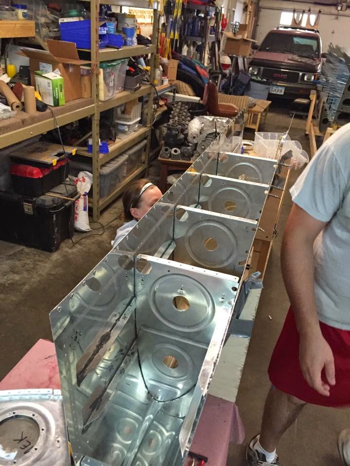
L and R tanks, respectively after the last of the ribs had been installed
Close-up of R fuel tank inboard rib. From left to right, you can see the vent fitting, return fitting, and feed flange; as well as custom access panel cutout (bottom) and fuel sender cutout (top)
Close-up of L tank, mirror image of R tank above
Inside of R tank inboard rib
Inside of L tank inboard rib
Once that was done, I got out the coil of vent tubing and realized... doh! We were supposed to install the vent line before riveting the inboard rib into place to facilitate feeding the line through all the ribs. Actually, it wasn't very difficult to feed it through anyway, it just went slower and took a little more care. Next thing to do was get started on a fuel tab. Although it's not in the plans, I figure it would be really useful to have tab sticking down into the fuel tank from the filler neck to mark the 2/3 full point, like you see on some production aircraft. The trick is, how far down from the filler neck is really 2/3 full? Given the angles due to dihedral and angle of incidence the plane sits at on level ground, plus the airfoil shape of the tank itself, this isn't an easy question to answer. I had posted a question on VAF a couple days ago but haven't heard any responses... I suppose it's sort of an odd question and it would take someone to have to go out to their plane and measure. So, I'll have to take a stab in the dark on this. Ready for some Kentucky Windage? Here goes:
Given that the tank is about 9" tall at the baffle, if we were dealing with a square and level tank we'd want our mark to be 3" down from the top. Dihedral causes more fuel to settle near the root than at the filler location, but incidence angle/airfoil shape will affect it also. Best guess, 3.5" down from the filler neck should give us 2/3 full, within say 1/8 tank plus or minus. We'll see how good this guess was in another year or so, I suppose!
The fuel tab, 3/4" wide with lengths of 1/2", 3-1/2", 3/4"
Tomorrow, time permitting, we'll make the second tab and install them to our custom fuel cap flanges, along with the vent line holder!
Saturday, April 18, 2015
Fuel Tanks - Proseal bottle #4
Well, we didn't get to do nearly as much work on the plane this last week as we had hoped... I was on travel Mon/Tues, then Wednesday we were both pretty tired and decided to skip a day. Then Thursday our friend Martin offered to give us a ride in his Bonanza to MCW for "Third Thursday" fly-in BBQ and had a blast. It was our first visit to this event, we'll be back next month for sure! Fridays we usually take off from building, and then this morning we went up to IIB for a fly-in pancake breakfast at Walter Aviation. Unfortunately, only Sarah got to actually fly up due to one of the two rental planes our group of 6 was using had a dead battery due to the previous renter leaving the master switch on (aaarrrgh!). Have I mentioned before we can't wait to have access to our own aircraft?!?!? Really frustrating. So we ended up re-shuffling the group and the 4 lightest people still went in the one operational plane. That left me out :-( but I still drove up and re-joined the group for some pancakes and hangar flying. Sadly, shortly before we got there a Cessna 195 had ground looped on landing (~15-20kt direct crosswind) and although the airport remained open, the mood was soured a little bit due to that incident, and we didn't stay and chat as long as we sometimes do.
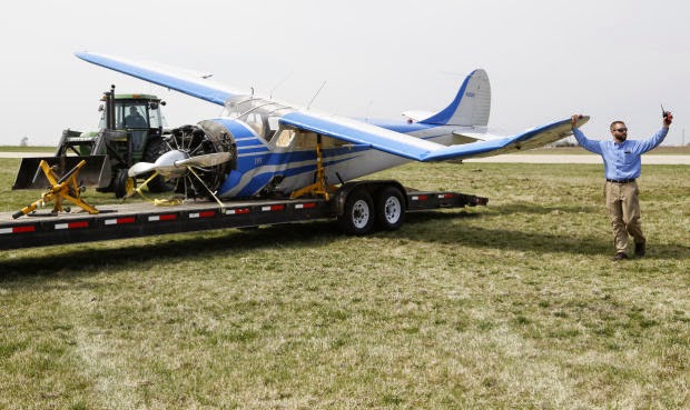
No one was hurt thankfully, but it's still a pretty bad day when you wreck a very beautiful and sought-after (not to mention expensive) aircraft.
Anyway.... after we got back home, it was time to shift focus back to the project!
Our friend Alec stopped over again to hang out and witness the "joy" of proseal. We installed the remaining ribs and stiffener into the L tank, which almost perfectly finished off the 3.5oz bottle. So far, four bottles have gotten both tanks to the same stage: ready to install vent line, fittings, and inboard ribs. Hopefully, we'll get to that tomorrow! For now, here's a few pics from Alec, who was on photo duty for the day :-)

A sad sight to see, just glad no one was hurt!
No one was hurt thankfully, but it's still a pretty bad day when you wreck a very beautiful and sought-after (not to mention expensive) aircraft.
Anyway.... after we got back home, it was time to shift focus back to the project!
Our friend Alec stopped over again to hang out and witness the "joy" of proseal. We installed the remaining ribs and stiffener into the L tank, which almost perfectly finished off the 3.5oz bottle. So far, four bottles have gotten both tanks to the same stage: ready to install vent line, fittings, and inboard ribs. Hopefully, we'll get to that tomorrow! For now, here's a few pics from Alec, who was on photo duty for the day :-)
Sarah and I posing for a perfect "action" shot building the tanks
Our dogs Dag and Mesa watching the fun
Alec and Sarah being silly... he loves to peel the blue cellophane off the parts, but apparently if he does it too much it gets stuck to his glasses...
Tuesday, April 14, 2015
Wings
Today Sarah started final-drilling the bottom skins while I was away on travel. No pics, but it's about 3/4 of the way done... that should make for an easy finish tomorrow, along with maybe another bottle of proseal... yay!
Sunday, April 12, 2015
Wings
No proseal today, we'll wait until maybe Wednesday or so I think for the next round. Everything in moderation, right?
Instead, we cleaned up the shop a little bit, and I put together a small utility cart we got from HF yesterday. I think it will be nice to use it to hold parts, tools, etc and help keep clutter off the work tables. We'll see how well it works. Certainly, in true Harbor Freight fashion, this thing was... well... "interesting" to put together. The quality of workmanship for the parts in this utility cart were not exactly at the same level as, say, Van's.
Other than that, the only real work on the plane was starting to match-drill the remaining holes in the bottom wing box stiffeners, and preparing for a massive final-drilling event to get both bottom skins complete. That should happen sometime next week, I believe!
***GOTCHA ALERT***
I'm going to start a new tag on this blog called Gotchas, with this being our first installment. On Page 14-6 for the Wing rib assembly (completed by us several weeks ago), there is ONE of the 24 bolts (per wing) that requires two washers stacked on each other instead of the typical single washer. The plans only call this out with a small "2X" mentioned in the parts listing, but it is neither depicted in the graphic; nor is it highlighted, flagged, or mentioned anywhere else in the plans. In my opinion, this is an extremely easy detail for a builder to miss. They call for two washers here in order to keep the nut from reaching the end of the threaded portion of the AN3-20A bolt to be used. I missed this callout when assembling the wing ribs, and the tolerances here are so close that using just one washer will still barely snug up on the two parts (as the nut reaches the end of the bolt threads) just as you reach 25 in-lbs torque on the bolt.
Step 14-6, with the bolt in question circled
You could probably use a shorter bolt instead (like an AN3-17A) with one washer, but I think the reason Van's did it this way is so that the shank of each bolt protrudes all the way through the spar and rib flange, and the threads for each bolt begin past the rib flange. This probably helps with the shear strength characteristics of the fastener.
I doubt I would have ever caught this mistake, and I'm pretty confident it would have never been caught, had my Pitts builder friends Gary and Justin not stopped over to set a few rivets for their project and talk shop for a little while. We got into a discussion about bolt lengths, and I went over to demonstrate the way the spar and ribs had been assembled on our wings, when Gary just so happened to grab the ONE bolt (remember, out of 24) that was incorrectly done and was able to make it twist with his fingers. You can imagine my horror!
It took all three of us a good 20 minutes staring at this page of the plans, and checking our work to realize the problem. After quickly remedying the issue and dabbing an emotionally comforting extra-thick blob of torque seal on the bolt, I showed the plans to another friend of mine who specializes in engineering/installation drawings and diagrams for retrofitting the big jets (Boeing/Airbus) with electrical upgrades. He was appalled by the lack of a flag or some other highlight to point out the discrepancy for that one bolt versus the others, and recommended I contact Van's to suggest they highlight this step a little more clearly. That made me feel a little bit better, and I might just do that... but for now I wanted to at least document this finding here on the blog.
The good news here, folks (read: mom) is that I don't believe this one bolt being out of tolerance would have caused anywhere near a 'real' safety hazard for the airplane itself. With the skins riveted into place, and 23 other bolts and 81 more rivets holding the ribs to the spar, it's not as though the whole wing structure was compromised by this one bolt not being fully snug against the parts. That being said, it wasn't fastened as well as Van's engineers wanted it to be, and that is indeed not a good thing. Care needs to be taken to ensure you don't miss these kinds of details hidden in the plans, and plain and simple we failed with that here. I'd be willing to bet, though, that there's more than one RV-10 flying around out there with a missing washer in this location.
Saturday, April 11, 2015
Fuel Tanks - Proseal bottle #3
Woke up earlier than normal for a Saturday morning, feeling energized and ready to take on the world. Nothing can ruin that feeling faster than deciding to dive into another round of proseal :-)
In all seriousness, I guess you could say I'm coming around with this stuff. It really isn't THAT bad, it just takes some preparation and organization to keep the mess under control. Also, we're definitely getting into the rhythm of working together on the fuel tanks, and for the most part the assembly process is going quite smoothly. I'm still pretty nervous about leaks though, and that fear hasn't been diminished any by reading all the horror stories on the forums. I think once we finish with all the ribs and are ready to install the baffle, we'll run another fillet around all the seams and any potential leak spots just to keep our 'i's dotted and 't's crossed.
Today, this third bottle of sealant got us through the remaining R tank ribs, as well as two more ribs on the L tank. I think the fourth bottle should finish off the ribs and remaining stiffener for sure.
L tank ribs 2&3 riveted into place
R tank ribs complete!
R tank outboard end rib with fillet
R Outboard tank bay
R tank outboard end rib, from outside
We then spent the rest of the day making a Harbor Freight run for more disposable gloves, had an afternoon family birthday party, and finished off the day with a quick joyride flight to Platteville, WI and back. It was too beautiful of a day to not go up, even just for a bit.
Sort of off-topic, but had to post this here. Last night we went out for a beer with some friends after work, and Sarah's story of drilling through the tank J-stiffener into her finger came up. In order to re-enact how it happened, she improvised a tank skin and J-stiffener using a napkin and a piece of celery. Brilliant use of props!
Sarah demonstrates her technique drilling through a napkin skin and celery stiffener
Tomorrow, maybe more proseal? We'll see....
Thursday, April 9, 2015
Wings
Had a few of the first spring storms roll through the area tonight and didn't feel like chancing it by embarking on a non-stop 3-hour commitment with proseal. So instead, we had a pretty easy night continuing on Section 20 with the wing bottom skins. I had previously clecoed the gap fairings into place, so we made quick work out of final-drilling all the #40 fairing-to-top-skin holes on both wings. Still need to do all the #30 fairing-to-rear-spar holes, because apparently changing a drill bit was beyond our motivation at the time.
Also, we hung the bottom skins and started clecoing everything into place. This is definitely reminiscent of the top skins!


Also, we hung the bottom skins and started clecoing everything into place. This is definitely reminiscent of the top skins!
R bottom skin starting to be clecoed into place
L bottom skin starting to be clecoed into place
Last thing from tonight was I decided to cut out the hole for the pitot mast. I have the SafeAir pitot mast from Avery tools (link here) and have also bought the Garmin GAP26 heated pitot/AOA. I've decided to mount it in the #2 bay inboard from the tip, using the outboard-most 3 rivets within that bay. The mast comes with a template that helped position everything and draw a cutout line and two drill holes in the skin, although I feel like the template was at about 95% scale of the real thing. That didn't affect much, except once I had the hole cut out I had to run another pass with the dremel to enlarge it again so the mast would actually fit. I didn't take any pics during the process (oops) but here is the final product, clecoed into place:
Pitot mast clecoed to L bottom skin, second bay from tip
Different angle of the pitot mast installed
The mast is fairly long compared to other models, but I'm not sure if I want to cut it down or not. There is certainly enough clearance to work with, and I'm figuring the farther the pitot is from the wing, the less error will be induced. Most likely we'll leave it as-is.
Probably take Friday off from building as usual, Saturday probably get through at least one more bottle of proseal, and then maybe Sunday do some final pre-baffle installation prep, including plumbing the vent line, rivet QA/redos and installation of my home-brew capacitance probes. Oh yeah, and we still have to prime the external tank parts like the zees, half the inboard support bracket, and a small handful of miscellaneous parts. Maybe we'll throw the wing gap fairings into the batch too while we're at it. I have some work travel planned early next week, but hoping to have the tanks done by the following weekend!
Subscribe to:
Posts (Atom)