Sunday, November 29, 2015

Long Weekend

Unfortunately this weekend marked a rather sad moment in our lives. We had to say goodbye to one of our two beloved four-legged friends, Dag, a.k.a. "Daggles" "Dagelope" "House Horse" "Bignose" and a number of other nicknames. Over the last few months he was battling a fight with cancer, and on Friday it was time to put an end to his suffering. He will be greatly missed by all who knew him, and has left a void in our household that won't soon be filled.

Although we did get a few odds and ends done on the plane this weekend also, nothing really worthy of mention at the time being has happened, and I'll fill in a few of the blanks as we continue. For now, I'll end this post with a pic Sarah put together for the one and only Mr. Daggles. He didn't always wear a costume, but when he did, he owned it. We'll miss ya buddy.

R.I.P. "Dag" 2007 - 2015

Thursday, November 26, 2015

Cabin Cover

Happy Thanksgiving! In between sleeping in this morning and getting ready to go do the family thing this afternoon by making my spinach and artichoke dip, we found some time to wander into the garage and continue on the cabin cover.

Lots of sanding and mess-making! Wow the sides along the door sills need to be trimmed down to almost nothing. Like many builders before us, we are unimpressed with fiberglass work. It's dirty, it smells funny, and you have to wear breathing masks and eye protection and all that stuff. In the end though, we were able to sand away enough material to get the cabin cover to slide all the way down and into place... ok, it was worth it!

Cabin Cover fits in place for the first time!

Still LOTS more sanding and fine-tuning to do, but this is pretty close at least for the initial fit. Definitely worth stepping back and admiring our work!

Ok, now on to more important things for the day... gotta go make that dip and go eat some turkey. More building to come this weekend!

Sunday, November 22, 2015

Empennage Attach

So while we wait for the next good time to continue with the cabin cover, I thought I'd try something new and continue with some other unfinished business, such as attaching the empennage to the tailcone. Technically speaking, this task is part of the Empennage kit plans as Section 11, and could have been performed LONG ago before we even started on the wings or fuselage. However, many builders don't do this until even later in the build than we are, and wait to attach everything for the first time until the plane is in its hangar and ready for final assembly. I think it will be advantageous to attach the tailfeathers now and get an idea of what we're up against before moving to the hangar.

Fetching the empennage plans and turning to Section 11, I got started. Basically, you need to secure the horizontal stabilizer to the work table and attach each elevator, one at a time, to do some alignment, clearance checking and drilling. Then, you attach both elevators and match-drill through the control horns so that both elevators are perfectly aligned. I didn't take too many pictures of the entire process, but here's at least a few:

L Elevator installed for drilling

L Elevator attached and moving for the first time

Duct tape holding the elevator in 'trail' position for match-drilling the control horns

The process went pretty well altogether, and before long we had two elevators and a horizontal stabilizer ready to install to the fuselage. Next, it was time to start the attachment process. First, the horizontal stab gets clecoed into place, and then some more match-drilling and alignment is performed.

Horizontal stabilizer clecoed (and now bolted) into place on the aft deck

Starting to look pretty cool back there!

The trickiest part of this process was aligning the horizontal stabilizer to be straight and true. The plans have you take a long piece of string and attach it to a center rivet hole further forward on the tailcone, and ensure that you have the same distance between there and each aft corner of the stab. The initial measurement was off by just a gnat's eyebrow, so a little tweak with the clamps holding everything in position made the second measurement fall perfectly in line. Match-drilling things together permanently placed it into alignment!

Next, things started to come together pretty quickly. I fetched the rest of the empennage parts and was able to perform all the steps of attaching the vertical stabilizer, elevators, and rudder in fairly short order!

N165MJ with tailfeathers attached for the first time!

We're going to need a higher ceiling...

Wow! Although these parts have been built for a long time, it's pretty impressive to see them all come together on the plane and actually make it actually look like a functional thing! So, we played arouind with the elevators and rudder for a bit, and called it a night. Awesome day of pretty rewarding work!

Next time, I think we'll probably be back to fiberglass work... womp womp.


Thursday, November 19, 2015

Cabin Cover - First Cut

We accomplished the first cut of the cabin cover tonight... woohoo! It went mostly "okay"... definitely a big gear shift from all the aluminum metal work that we've grown accustomed to. Sarah will be involved quite a bit more these days too, since she has earned the esteemed title of "fiberglassing expert" on this team (you may remember from one of our first-ever posts about the EAA SportAir Workshop we attended, I took the sheet metal course and Sarah took the fiberglass course). In truth, we both have a lot to learn about fiberglass work, and we'll be taking it slowly and carefully, and hopefully not end up splitting the cover in half or something and end up needing to order a new one. I'm fairly certain this thing isn't cheap.

So with that, it was time to get started! We donned our dust masks and safety glasses, got the shop vac ("R2") handy, and grabbed our secret weapon: a Dremel MultiMax oscillating saw. Sarah mentioned that they used one of these in her fiberglassing class to cut cured pieces, and it cut through them like butter and made very little dust. Excited to see how it works!

Team Mike & Sarah ready to cut some 'glass!

Moments after this photo was taken, we discovered that the oscillating saw works TERRIBLY on the cabin cover. It bounces all over the place and barely made any kind of cut at all. On the bright side I guess it didn't make much dust either, so it did live up to that end of the bargain. So, we went back to the normal plan and grabbed the air cut-off tool. After installing a fresh cutting disk, we got started. In a demonsration of her multi-tasking abilities, Sarah took this video of the first cut while holding the vacuum nozzle:

First cut of the cabin cover!

It's a relatively slow process, and even though we have a decent-sized air compressor, I've long known that it isn't quite big enough to run the air-hungry cutoff tool continuously. It will go for a minute or two but then runs out of steam and needs a few minutes to recharge. No big deal, just something to be aware of. After a handful of cut/recharge cycles, we had made all the necessary cuts to attempt an initial fit of the cover!

Initial fit of the cabin cover - doesn't quite slide into place yet!

Nowhere near enough yet! That's ok... hey, at least we didn't cut off too much. Now it's going to be many cycles of cutting and sanding, trial fitting, and figuring out where the high spots are that need more cutting and sanding. This was enough for one night... but we'll get back to this soon!


Wednesday, November 18, 2015

Cabin Top Prep

Not a whole ton of work on the plane today, but what wasn't accomplished physically was certainly made up for by overcoming the mental hurdle of transitioning to fiberglass work... today marks the first day of Section 43 - Cabin Cover!

Although no actual "fiberglass" work started yet, we did rearrange the shop a bit and perform the first few steps in the section, including marking 7 spots on each of the mid cabin decks, and marking off all the scribe lines on the cabin cover itself. I now see what people are talking about when they say the scribe lines aren't really all that great-- they're definitely not very straight and I think they only give the general idea of what needs to be cut!

Marks on the mid cabin decks for eventually match-drilling the cabin cover screw holes

Traced the scribe lines with a blue Sharpie to denote the first cut lines


An interesting step cut that will have to be made

Not all the scribe lines were very straight!

So that's pretty much it for today, but tomorrow we should be able to actually start cutting and sanding this thing.... eeek!!!!

Tuesday, November 17, 2015

Financing

I'm going to touch on a slightly "taboo" subject today... money.

So this is going to be another mostly off-topic post, at least as far as "building" the plane itself goes. However, you can't build a plane if you don't have the necessary parts and tools, and you can't buy parts and tools without money. Let's face it-- flying isn't exactly the world's cheapest hobby, especially if you want to own your own airplane. Even more so if you want that airplane to be nicer and newer than most rentals, and have some of the common "luxuries" you'd expect in a vehicle of any kind that costs north of six figures. Yes, building it yourself makes it more affordable than a comparable factory-built plane like the often-compared Cirrus SR22, but most of us builders don't really go this route based on financial reasons alone. Any way you slice it, you're in for a pretty hefty chunk of change by the time you get your fancy new RV-10 into the air.

That being said, you don't necessarily have to be "rich" to build your own airplane, either. We're not, anyway. Our house isn't anything fancy, and we drive beater vehicles straight out of an easy listening radio station (70's, 80's and 90's). I suppose I do have a pretty good job working as a software engineer, and yes it pays fairly well, but money doesn't exactly grow on trees around here either. I assume many other builders are in a similar situation... doing well for themselves but not exactly in a position to just shell out the money necessary to build a plane in hard cash. If you are one of those people, you're lucky, and feel free to skip the rest of this post. :-)

For the rest of us, we need to figure out a way to fund the project. Of course, strolling into your local bank and asking to speak with a loan officer, telling them you want to build an airplane in your garage, and that you need six figures of unsecured funding will make someone's day, but probably not yours. There are a small handful of financial institutions around the country that do specialize in aviation loans, and an even smaller subset of them (I've found precisely two, one through EAA and another through AOPA) that offer some sort of "aircraft construction loan" specifically for experimental aircraft. The good news here is that these companies absolutely love RV's because they have exceptional market value and excellent safety records, and are easy to assess. This translates to getting the best-case possible loan terms, which is great. However, these loans still have some pretty significant strings attached, with some examples being you need to purchase full hull in-flight insurance coverage the moment you sign the loan (big premiums, even though the plane isn't anywhere near flying condition yet), you must maintain xxx (high) amount in your checking account, and/or they need to send disbursement checks directly to the vendors to buy ALL the parts for your plane within 30 days (impossible, there are many purchases to make over many months from many vendors). Additionally, while the interest rates weren't "bad," they weren't really "great" either. So, I never ended up applying for any of these aircraft construction loans.

What I did end up doing was sometime last year I put together an incredibly complicated Excel spreadsheet (that only I understood) and planned out a revolving credit line sourced from a handful of decent-rate and high-limit credit cards, and a home equity line of credit (HELOC). I whipped up some rough numbers for time and cost, estimating the fuselage would be ordered here, the finish kit here, the engine overhaul here, etc etc. By the time the numbers came back, I had a plan that would "just barely work" by riding out the HELOC and credit cards in this gigantic torrent of revolving debt that I had concocted.

This plan has worked, in fact with a great deal of success, up to this point. Actually, it would probably continue to be successful up until completion of the project. However, it isn't ideal in my mind, and some of the credit cards involved have higher interest rates than I'd prefer. So, while continuing with this plan, I've been slowly and silently searching for a Plan B that might make things go easier for us.

In comes SoFi. Haven't heard of SoFi? Me neither, at least I hadn't until a few days ago. I got a random solicitation from them in the mail last week... you know, the ones you typically can just tell from the outside of the envelope that it's going to be in the trash in about 10 seconds. For whatever reason, I opened the letter first though. It sounded too good to be true, you can apply for a personal (unsecured) loan online in just a few minutes, and within a few days have your new loan direct-deposited in to your account. Oh yeah, and the rates were incredibly lower than any other similar loan I could find, including even the many-strings-attached aircraft construction loans. The amount you can borrow was astonishingly high too. No application fees, closing costs, origination fees, early repayment fees, fees of any kind! Ok, what's the catch? I started reading up on SoFi online and researching all that I could about them, and read all the fine print, and still wasn't scared away. Worst reviews I saw online about them were that they could be pretty selective, and they would sometimes drag on the approval process for a long time and request all kinds of documentation, and then ultimately turn you down. My credit is very good but not unrealistically high or top-echelon by any means, but I thought what the heck, I'll apply and see what happens, what's the worst that could happen?

Here was my application experience, literally: I went to the website and followed the steps to apply for a personal loan. They needed precisely *two* documents: a current pay stub and a scanned copy of my passport. Within 10 minutes, the application was complete and it was in for the approval process. Within 48 hours, I was approved and had the funds sitting in my bank account. For taking 10 minutes out of my day, I've just sliced my interest rates in half and fully funded the rest of my build, with plenty of headroom to spare now. What's significant about this is that the amount and terms of this loan are completely untouchable by any other bank I have seen, plus because it's a personal loan they don't even need collateral in the airplane. The rates are *almost* good enough where I just might consider not even refinancing when the plane is flying!

If you're in a similar situation as the one I described above, I'd highly recommend checking out SoFi. You can even click a referral link here, and you'll get $100 (I'll get a few bucks too). If doing the referral thing isn't your thing, I understand, honestly I always tend to roll my eyes at these kinds of deals. So here's a link to just go to their website at sofi.com, Either way you might find a surprisingly good deal. I know I did.

That's all for now.. next time we catch up I just might start finally attaching the cabin top to the fuselage!!!

Sunday, November 15, 2015

Control System - FCP Pod - Magnetometer Mount

Busy weekend mixed with both "real" work and "plane" work. While I had some time to slip out into the garage, I was able to finish the control system by installing all the pushrods and control sticks for a clearance check with the fuel filter and fuel lines. With the straight fittings coming out of the fuel filters, it will be "close" in certain stick positions, so I'm going to play it safe and change them out for 45-degree fittings, which should make a pretty big difference. For photo purposes, I also grabbed my Tosten stick grips and stuck them on each side to get a first rough look at what the controls will look like:

Control Sticks installed with Tosten stick grips

Closer view of sticks and stick grips-- note clearance with R fuel filter

Of course, the sticks will have to be cut down quite a ways to be the proper length with these grips, but it was still pretty cool to sit in there and move them around a bit. The "trigger" button on the grip is normally wired as the push-to-talk button, but until that actually happens, we will refer to it as the "pew-pew-pew!" button. :-)

That was pretty much it for yesterday. Today, I started making a "pod" for the GMC-307 flight control panel. The master plan is to make a panel which measures approximately 9" x 2.5" and stand it off about 1.5" from the main panel, and contour it up to the top skin of the upper forward fuselage. The panel will fit (tightly) the GMC-307 control panel, as well as a custom annunciator panel with 4-5 warning lights on either side of the FCP. You may have seen pics previously of the mockup, where the GMC-307 is hanging down from the top... this is the general idea, but now I need to build a pod that actually mounts the thing in that location.

Unfortunately I didn't take any pics of the construction process (I was "in the zone") but here's a few photos of the finished product:

GMC-307 mockup and annunciator pod clecoed together

Back side of pod that will permanently rivet to the panel (and screw into the top skin)

Pod with front panel removed

Pod partially clecoed to the main panel

That's basically the idea of it! It all seemed to go together fairly well (although it took quite a long time to build), and with some upholstery over it I think it should look pretty sharp. We'll see. A lot of this is only visible in my head for now and hasn't yet been proven to work in the real world, so lots more to come on this.

In other news, I got started on making a mount for the magnetometer. It seems the consensus for mounting location for the GMU-22 is in the tailcone, along the top stringers and near the static ports. I again found myself on Justin Twilbeck's site and read up on the method he used to fabricate his ADAHRS tray, which he later changed to a place to mount the GMU-22 instead. Taking both of his posts (original design here and GMU-22 mod here) I made a tray similar to his first design but taller and with a few other modifications. Again, I failed to take pics of the construction process but here is the final piece:

GMU-22 tailcone mount

Basically, the tray is about ~3" down from the tailcone top skin, and the tray is approximately 10.5" wide. I cut a 2-9/16" hole in one side using a fly cutter (remember there is a center stringer in the tailcone) to eventually mount the magnetometer itself. The stiffeners are installed on the top side of the tray instead of the bottom also, for better clearance with the side plates. I made it so that the side plates each have an angle piece and two #12 holes, such that the mounting plate can be slid in on top and over the angle pieces, and then bolt into place with brass hardware. This way, the relatively weak non-ferrous hardware will only be loaded in shear, and should have no trouble holding the magnetometer in place. Cool! Now just for some primer and rivet the three individual pieces together.

That's pretty much it for the weekend. More panel planning, fuel system layout, and miscellaneous "stuff" to come!


Thursday, November 12, 2015

More Fuel System

Fuel lines in the tunnel are done tonight! Now just have to finish up the "easy" ones under the seats. Not much to write about tonight really, but I will leave  you with a few pics of the current state of affairs in the tunnel:

Mid tunnel cover installed with fuel selector

R rear tunnel section showing lines going around parking brake valve and control system cutouts

L rear tunnel section, these lines were much easier to route!

View from the rear of the tunnel looking forward towards the fuel selector

View from the front of the tunnel looking rearward towards the fuel selector

Aux tank feed entering tunnel and "swooping" aft and down to pass under the other two fittings


There are a few things that still need to squeak by all these lines: Rudder control cables, throttle/mixture/prop control cables, and a 2" SCAT tube for the rear ventilation. I *think* there's enough room for everything, we'll see. I think the biggest challenge is going to be getting the throttle/mixture/prop control cables routed around the fuel selector because they will be in close proximity to each other and there are a good number of fuel lines to get in the way. Hopefully we'll be able to figure out a way to make things work!

Next on the agenda is to finish the fuel lines under the seat areas, and then disassemble all the lines and prepare for final-assembly of the fuel system!

Wednesday, November 11, 2015

ELT - Flap System - Antenna Mount - Misc

Happy Veterans Day! It's been an interesting year, getting used to my new job where we observe all of the federal holidays and have the day off. Not that I'm complaining of course... more time to build! :-)

Today was an excellent day making progress in a number of areas. I started off by installing the ELT mount in the tailcone, which went fairly quickly even though it was a bit tough getting access to install blind rivets in all the holes between the mount and the J-stringers behind it. I ended up stacking two #6 locknuts on the rivet stems so that my rivet puller could get the grip it needed for the job. About 20 minutes of this combined with some awkward leaning, and the mount was in!

ELT mount installed, sans ELT

ELT mount installed, with ACK E04 ELT

Cool! Looks "official" now. You may notice that the mounting tray is not parallel with the tailcone stringers. I'm using the door sills as a reference for level, and discovered that the stringers in this location actually slant upwards just slightly. I used a level to approximate the angle here, and I believe it turned out pretty darn close. I have a 10-degree tolerance per the installation requirements anyway, and I'm confident that it's well within that. (EDIT 11/15/2015: A tip I later discovered, kind of an "oh, duh!" moment: if you have a smartphone like an iPhone with a compass/level app, you can use it as an inclinometer and get very accurate measurements to the nearest degree! Turns out this ELT is approximately 2 degrees off from perfection. Well within tolerance, but I could have done it perfectly if I had been thinking!)

Next on the agenda was to start assembling the flap system. Oops! Quickly discovered that before I do any final installation in this area, I'll need to install my belly-mount COM antenna doubler that I want to put in this location. So, on to that.

I chose this location for the antenna for a couple reasons. First, I wanted the antenna to be in the tunnel area so that it is always accessible from the inside. I've seen a number of builders (the majority, in fact) use the area under the rear seat to mount a COM antenna, but that just doesn't sit well with me. If you ever have to gain access to this area for whatever reason, you'll be drilling out hundreds of rivets and removing a pretty large part of the cabin floor. So I made the decision early on to put all the belly antennas in the tunnel area (I think there will only be two: this COM antenna, and a transponder antenna further forward).

The second reason for choosing this *exact* location in the tunnel beneath the flap torque tube is a bit of  accidental chance. Way back when we were first joining the forward and mid fuselage sections together, Sarah had a bit of an "oops" moment with the tungsten bucking bar, which had slipped from her hand and went flying through the air. In a slow-motion "noooooooooo!" sequence, fate steered the bucking bar's trajectory straight toward this area of the tunnel, resulting in a solid "clunk!" and producing a nasty outwards dimple in the bottom skin. We learned two things from this event: (1) Install an antenna in this location; and (2) secure the bucking bar to Sarah's hand with duct tape. Just kidding, of course. We weren't actually sure if we would install an antenna here yet ;-)

Reading some of the other build blogs online, I discovered that fellow RV-10 builder Justin Twilbeck actually had a similar mishap (see his blog post "Dent Happens" here) and decided to put an antenna at the scene of his accident as well! Funny coincidence.

Anyway, this location actually works out perfectly, as it is right at the "hip" of the fuselage, at the aft-most part of the bottom before it takes a turn upwards. I believe it really is actually an ideal location. So, I got started on making a doubler to place over it. I found a template for the hole pattern for the Comant CI-122 and used it to start making the doubler, and ended up with this part:

Comant CI-122 doubler, prior to enlarging circled holes for antenna connector and mounting screws (also added another row of holes near the left side in this photo)

After a bit of match-drilling to the fuse bottom skin and enlarging the holes, I was able to shoot the piece with primer quickly and await Sarah's return home from work to finish dimpling and riveting the piece into place. In the meantime, I continued with some miscellaneous tasks left over from the previous sections, including running some conduit along the right side of the baggage area and installing the cover panel, as well as installing the cover panel on the left side of the baggage area behind the rear seats. Lastly, I installed a number of nutplates that go in the various locations along the interior of the fuselage to secure cover panels and such. About this time, Sarah got home and we proceeded to dimple the bottom skin and rivet the antenna doubler into place:

Antenna doubler installed in tunnel. Antenna is offset slightly to provide clearance for elevator push rod, visible on the right

Comant CI-122 screwed to the bottom of the fuselage

Looks neat! I didn't have long enough screws for a permanent installation, but they worked perfect for a trial fit. Seems pretty solid and sturdy here and should work great!

For the final chapter today, I finally got to what I had set out to do earlier today, which is to install the flap system. I had already drilled and prepped most of the parts on a previous day, so today it was really just all about installing everything into the plane. I quickly discovered my first issue, which was that the holes in the fuselage side skin were too small to fit the flap torque tubes. I couldn't figure out any other way to get both tubes into place, and ended up enlarging the skin to match the underlying holes at 1-1/16". Then the next challenge was installing the UHMW bushings and getting everything oriented properly. I discovered another problem: the cutaways for the powdercoat weren't exactly in the correct locations on the torque tubes! This caused a huge increase in friction, and the tubes were very difficult to rotate.

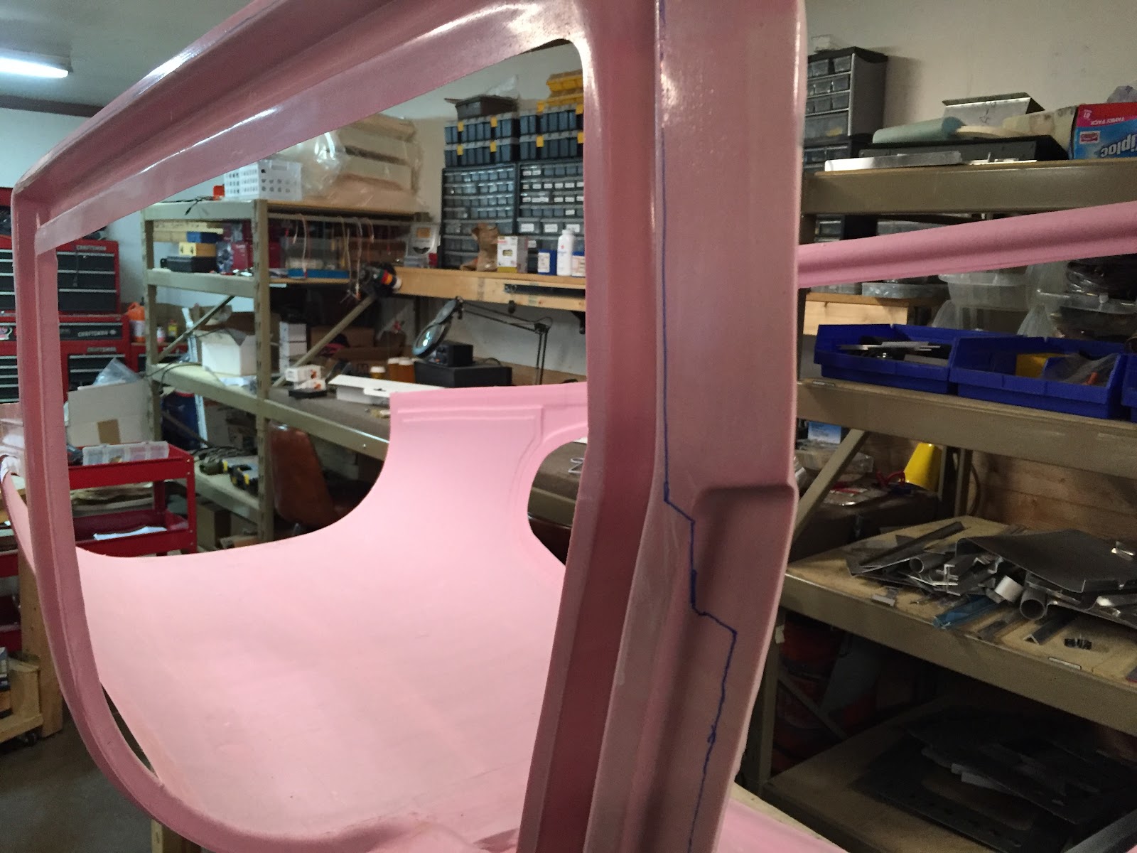
L torque tube inner end, line drawn where bushing extends to

Each of the four locations had varying amounts of overlap, so I traced lines on all ends and carefully ground away the powdercoat, and polished the surfaces on the scotch brite wheel afterwards. Re-installing the tubes showed a dramatic reduction in friction! Good stuff.

So after about an hour of bolt-installation and rigging, we had the whole works put together!

Sarah is happy. Please move your hand though so we can see!

There we go! Flap system installed and ready to go

Sarah wanted to take a picture of me tightening the last bolt holding the actuator to the torque tube arm (visible above with no nut)

With that, we were able to hook a drill battery up to the flap motor and presto... The flap arm appears to work perfectly!! Wahoo! This is the first electrical part that is permanently installed to the airframe now. Exciting times. We ran the flaps up and down a couple times until the excitement wore off a bit and decided to call it a night. Big day of building today, and all ended up going very well! Tomorrow if the UPS gods are shining on us we should get some more fittings to satisfy our insatiable appetite for Aircraft Spruce packages, and we can continue with the fuel system. Maybe we'll also get to install more of the control system, even the control sticks! 'Stick' around!!


Tuesday, November 10, 2015

Rear Seats - ELT Mount Part 2

Finished Section 42 tonight! Yikes, running out of things do to in the fuselage kit short of the Cabin Cover. Got some time in over lunch today for a quick priming session. Primed the components for the rear seats, the elevator control rods, and the ELT mount that I had fabricated the other day. Got back to it after work and was able to rivet the rear seats together in fairly short order. Unfortunately Sarah had to proctor a pilot exam at the airport so I was flying solo tonight, so to speak. Derek came over for a bit to watch the excitement though, and before long both rear seats were set into position!

Custom 60/40 Rear seats, riveted together and laid into place

Right "40" seat leaned forward to show split

The whole assembly took about an hour, maybe less, to rivet together... awesome! Getting good at this riveting stuff, now that we're getting close to being done with most of the rivets on this plane. Oh well. Next thing to do was rivet together the ELT mount, which looks like this:

ELT mount riveted together

It's a fairly simple part made out of 0.063" aluminum sheet, two angle aluminum pieces to mate up with the stringers in the tailcone, and a short piece of J-channel going vertically between the angles. I'm not sure if I needed to use aluminum as thick as 063 but I had been dabbling with that thickness for the panel, had some scrap handy and figured why not. I think I could have probably used 032 and an extra J-channel instead, and saved a fraction of an ounce or something in weight. I would like the ELT to be mounted as securely as possible though, not only for obvious reasons, but also if we want to follow DO-204 compliance standards, taken from paragraph 3.1.8:
"The mounts shall have a maximum static local deflection no greater than 2.5 mm (0.1 in) when a force of 450 Newtons (100 lbf) is applied to the mount in the most flexible direction.  Deflection measurements shall be made with reference to another part of the airframe not less than 0.3 m (one foot) or more than 1.0 m (three feet) from the mounting location."
I'm not sure if I've heard of anyone ever actually test this, but the point is we want it to be as solid as possible. I believe that this part should easily satisfy this requirement. Anyway, that was pretty much it for tonight... I have tomorrow off from work so hoping if all goes well it will be a big day in the factory to make some good progress!!!

Monday, November 9, 2015

More Fuel System - Revised Diagram

Continued working with the fuel system tonight. Actually, it started earlier today when I sent off a few emails asking for price quotes for a number of braided stainless lines to go between the fuel selector and the various attach points. I got quotes back from two of the three places I asked, with prices ranging from $500 to almost $1000! For 8 hoses, each no more than 2' long. Ouch.

So I got to thinking, do I really "need" flex lines to go to the selector? It might be nice, but it is by no means a requirement. It may actually be better without them, because the fuel selector would be suspended in space in a fixed location, with the six hard lines going to it. Then the tunnel cover will come down over the top of it and screw to it. I think I'll try to go this route, or at least see if we can make it work before shelling out a ton of cash for some unnecessary "bling" that will be concealed beneath the tunnel cover anyway.

I started by making two hard lines going from the send and return fittings previously installed in the tunnel last night. Just those two lines were enough to hold the selector valve rigid in space in the correct location. Nice! Now just to make 4 more lines. Oops, I'm running low on AN fittings again. Gotta place another order with Spruce and we're be back on hold for a few more days. No big deal. In the meantime, here's a revised diagram of the fuel system layout:

N165MJ Fuel System Design - Second Draft

This diagram is pretty similar to the previous one (link here) with a few minor changes. Most notably, the regulator (or pressure relief valve) has been moved into the tunnel, and taps off of the inlet to the mechanical fuel pump instead of the servo. I've also ditched the filter between the mechanical pump and servo in favor of a gascolator in a more conventional location. I also threw in a check valve on the aux tank feed and a few more fancy labels.

Labeled photo of current fuel system (masking tape covering 'tee' inlet and outlet fittings)

Since the firewall-forward portion of the system is still TBD, the only part of the diagram that has been semi-finalized is the portion within the tunnel, visible in the photo above. The plan, however, is to run the "Send" line up to the inlet of the mechanical fuel pump, and tap off a "Return" line back to the firewall at that location. With this design, a failed relief valve would only affect the boost pump and not the mechanical pump. In this way the engine cannot lose pressure without a dual failure of both the mechanical pump; and the boost pump and/or the relief valve. This type of reliability is now identical to a traditional aircraft fuel system, with a significantly longer purge/return path. More importantly, the system is still fully forward-compatible with upgrading to an EFI system in the future if/when we go for that.

The only design limitation I can think of is that the boost pump should not be run with the fuel selector in the OFF position (and the mixture in cut-off position). This would result in a condition known as "deadheading," where both Send and Return lines are cut off, resulting in the fuel not being able to go anywhere and causing a spike in pressure. This is a condition that should really never occur anyway, especially while in the air, and the only thing that would happen in this scenario is a tripped breaker for the boost pump. Likewise, fuel cannot be transferred into the system from an auxiliary tank in this configuration for the same reason. That seems intuitive enough, though... fuel gets transferred into the selected tank, so if the selector is OFF then no fuel can be transferred! Also, there is no reason to run the boost pump with the fuel selector OFF, either. This will be placarded though, just to be clear and thorough.

That's pretty much it for tonight! Not much building really... a lot more thinking and planning, with a side of ordering more stuff from Aircraft Spruce. Tomorrow, I feel, may consist of a bit of a priming session if we're lucky! Stay tuned...

Sunday, November 8, 2015

More Fuel & Brake System

Finished the brake lines (Section 36) including the parking brake valve today! I ordered a 3' long control cable from McMaster (P/N 3125K44) along with a clevis and control knob, and fabricated a mounting bracket for it to attach to the tunnel wall and actuate the parking brake lever. Everything lined up as planned and it seems to work perfectly! I secured all the brake lines in place and tightened the brake valve mounts and took a few pics of the brake system:

Brake lines and brake valve in tunnel

Brake lines terminated on firewall

Parking brake valve with control cable mounted in place.


Demonstrating the clearance between the elevator/aileron controls and the brake valve/control assembly. In a worst-case scenario with the aileron control rod touching the bottom of its cutout, there is still about 1/4" between it and the clevis for the parking brake, which itself is in a "parking brake ON aka on-ground-only" position. The elevator control passes over the top of the valve with at least an inch or so of clearance.

This location for the parking brake valve should work fine... at least that's what I'm thinking so far. Next up was to start making components for the fuel system in Section 37. Since I'm "rolling my own" boost pump and return line, and also moving the fuel selector forward about 6" to make room for the armrest throttle quadrant, the fuel line measurements in the plans will be of little use other than to use as a general guide. The first thing to do is actually build the boost pump module, which I did by making two U-shaped pieces of 5052-O 3/8" aluminum tube:

Check valve (left) and boost pump (right) connected via two U-shaped tubes and fittings. Inlet is at the bottom tee, outlet is at the top.

The black jacket over the pump is an insulation sleeve I found online for fuel pumps, and it should help the pump run both cooler and quieter. Next, I started with the task of mounting the pump assembly and the pressure relief valve into the tunnel. Sarah and I riveted the two little pump mount brackets to the forward fuse bottom skin (deferred from way back in Section 28) in their normal locations. We had held off on riveting these before because we wanted to make sure we could make use of them and wouldn't have to relocate them or make a custom bracket. It turns out the standard locations work great, and we can put the boost pump module in the aft and center location, with the pressure relief valve in the forward location. This means the "send" line will exit the firewall on the L side of the firewall, and the "return" line will enter the firewall on the R side. So, with this plan in mind, I got to work getting it all installed.

Boost pump module installed in tunnel. Pump is secured via the standard hose clamp mounting method, and the check valve is secured to the L tunnel side with an adel clamp and #8 flush screw.

Larger view of the forward tunnel area, with both fuel Send (L) and Return (R) fittings visible below the heater outlets.

Next, more 3/8" 5052-O tubing had to be bent and installed between the firewall and the modules, as well as one run going back to a fitting on the rear R tunnel wall that will be the aux tank fill inlet. This line will be plumbed to a small panel in the rear seat area accompanied by a vent line and electrical connection. When an aux tank is installed, we'll be able to flip a switch on the panel to turn on a transfer pump inside the aux tank which will feed fuel to the fuel return line downstream of the pressure relief valve, allowing fuel to be fed into either the R or L fuel tanks, depending on the fuel selector.

Aux fuel inlet line visible above the rest of the fittings, with line swooping aft and then below the rest of the brake and fuel fittings. Also visible: tunnel entry points for fuel return and brake lines.

Aft tunnel area with everything installed

Forward tunnel area with everything installed

Boost pump module and pressure relief valve assembly close-ups. The taped-off fitting on the upper left side of the photo is the fuel inlet (from fuel selector send outlet), and on the bottom center is the fuel return outlet (to fuel selector return inlet).

Overview of the tunnel area from the firewall looking aft

That's pretty much it for today! Lots of good progress. The astute observer may notice a lack of pipe thread sealant on the exit side of the pressure relief valve, where there is a reducer and tee fitting for the fuel return and aux feed lines. I'll need to pressurize the system once and double-check the pressure setting for the relief valve, as it can be adjusted via a hex key inserted through this end of the valve. I figured it would be worth it to not seal these threads yet since they will likely be coming back off again anyway.

Other than that, I took some measurements for the stainless braided lines I'll need to buy to go from the tunnel entry points in the rear of the tunnel and up to the fuel selector, and also the two lines coming from the selector to the send and return lines. Until I can get them ordered and delivered, it's on to something else... maybe priming and assembling the back seats? We'll see!