Monday, August 31, 2015

Brake/Fuel System Design - Initial Plan

<<<I apologize in advance, this is going to be a long thread filled with lots of theories, ramblings and thoughts.>>>

So tonight instead of doing any actual "work" on the plane, I did some major research and planning on the brake and fuel systems. The brake system is fairly straightforward--at least the part in Section 36--which essentially runs two lines from the firewall area to the landing gear mount area. If you want to include the Matco parking brake, then it's a simple insertion into the lines "somewhere." Most folks install their parking brake valve on the firewall, but after reading a pretty descriptive (and hilarious) description from builder Myron Nelson about how difficult it is to reach the valve should it ever need servicing, I will be locating mine at the rear of the tunnel, where the brake lines diverge to go to the R and L sides. While unconventional, this location should be a lot easier to access in the future, and make for an easy control cable run in the tunnel. Pics and diagrams to follow.

Next, on to the fuel system. By far, this is the more complex, expensive, and thought-provoking system between the two. It is also a system that has been over-engineered and/or over-complicated by more than one builder, and sadly it is has also been at least a contributing cause for a number of fatalities in the experimental aircraft world, including the infamous accident that killed John Denver. There has even been one or two accidents involving RV-10's and poor fuel system design, although both of the ones I am aware of also involved highly modified automotive engine installations, which of course kind of throws all the usual stuff out the window to begin with. That's not what we're going for here.

What we ARE going for here though is what I'm going to call a "minor variation" on a tried-and-true system design, for two very specific reasons: (1) I am installing a fuel return line for future compatibility reasons, should I decide to install an electronic fuel injection system (e.g. EFII); (2) I will have provisions to connect a removable auxiliary fuel tank in the backseat or cargo area when extra endurance is required. Nothing too crazy, but any kind of modification needs to be considered very (and I mean VERY) carefully. So, we need to start with a standard RV-10 fuel system, analyze the crap out of it, and then (did I say carefully?) make our tweaks. So... keeping all this in mind, let's get started. Here is a diagram I made of a relatively standard, tried-and-true fuel system design to start with as a reference point.

"Standard" RV-10 fuel system design, IO-540 w/ Mechanical Injection

So I'm starting with this diagram above and calling it "Standard", but really there are already a few modifications depicted here. Notably, the check valves on each of the R/L vent systems, and individual pre-filters instead of the single filter at the boost pump module. The vent check valves are installed in each wing root and serve as a secondary vent, should the primary vent become clogged with ice (or a very unlucky bee). The individual prefilters simply separate the R/L fuel tanks a bit more, so that in the event one tank coughs up some really nasty gunk in the fuel and clogs the filter, you can still switch to the other tank and have unobstructed flow. These are two very common modifications that are pretty well documented already on other builders' sites, and I feel that they are both accepted pretty openly as safety improvements for protection against icing and fuel contamination.

So now, let's analyze the system a bit and look at the individual components, particularly the boost pump module. In the diagram above, the boost pump module is shown as three individual parts above the fuel selector: The check valve, the boost pump, and the regulator (or pressure relief valve). The way it works is best understood if we split into two distinct modes of operation: boost pump off and boost pump on.
  • Boost pump off: Suction from the engine's mechanical fuel pump pulls fuel through the check valve and forward through the system. Fuel can technically also flow through the pump and its internal check valve (if present) but we will consider that a path of more resistance. Fuel does not flow through the regulator.
  • Boost pump on: The pump pressurizes fuel going toward the engine, "forcing" fuel through the engine's mechanical pump and increasing system pressure, particularly at the inlet side of the mechanical pump, which is where vapor lock can occasionally occur. Due to this change in pressure, the check valve closes and prevents fuel from flowing backwards. Lastly, because the boost pump is capable of producing higher than desired pressure, the regulator opens for any excess of ~30psi and allows some fuel to return to the pump inlet.
Looking at the different boost pump modules available out there, I came across three different brands: The Van's-endorsed Airflow system, the Andair system, and the EFII system.

The ironically-named Airflow fuel pump module seems to have a number of happy customers, and it is Van's choice (always a plus), but it uses an Airtex fuel pump which is a brand I have quite a bit of personal experience with in the automotive world and regard them as inferior to just about any other kind out there. Furthermore, you can go buy the Airtex E2351 fuel pump used in that module for around $60, so I'm a little hard-pressed to cough up $500 to buy it.

The Andair pump looked awesome at first glance. Less external lines and fittings to go wrong, an internal regulator, and oh wow a BRUSHLESS motor! I've always wondered why brushless fuel pump motors haven't really caught on, it seems like they would be vastly superior to the traditional brushed motors in terms of both noise and longevity. Well, it turns out after reading a number of articles online about this particular pump that it is actually *louder* than others and there have been a number of failures, particularly early on due to some early design flaws. A rather disgruntled early-adopter made a video highlighting all the design flaws of this pump and posted it to Youtube, visible here. To be fair, it appears that the company has made improvements to the design since this time, and I am not aware of any recent failures of this pump. Even so, that was enough to make me move on, especially since this is the most expensive of the three options... the FPK-540 is priced at $850!

Finally we have the EFII module. This thing seems great-- it uses a Walbro brand pump (MUCH better than the Airtex in my opinion) and it has a custom check valve/regulator that boasts the lowest "cracking pressure" of the three available models. This means that the mechanical pump doesn't have to "pull" as hard to get fuel when the boost pump is off, which is a good thing especially at high altitudes or hot temperatures. And, it's very competitively priced at $649.

Between the three choices, to me the clear winner is the EFII module. There's just one thing left to consider though: the fuel return line that I have available on my system. If we take a second look at how these boost pump modules work, we can introduce an additional benefit that a true return line can provide. The way these modules are designed (in the absence of a return line) is that the regulator's return path is cut very short, sending fuel back only a few inches and re-introducing it at the inlet of the boost pump. With low demand from the engine (e.g. on descent), the majority of fuel follows this small circular path, absorbing heat from both the pumping process and the warm environment of the tunnel. Since we want our fuel to be as cool as possible for a number of reasons, this is not an ideal situation.

So, what if we pieced our system together instead of buying a pre-made module, using exactly the same kinds of parts as above, but allowed for the regulator to send fuel all the way back to the tanks? I spent hours online tonight, searching for pumps, check valves, and regulators, and I believe I have found a winning combination:
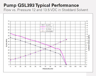
  • Walbro GSL393 fuel pump ($98.18). This is (I believe) the exact same model of pump used in the EFII boost pump setup. It has exactly the right spread of pressures and flows to exceed the demands of a 260HP IO-540 engine without going way overboard. The larger GSL392 pump is somewhat more popular in the automotive world but it has significantly higher output, which really is unnecessary here. The GSL393's performance chart can be seen here:
Walbro GSL393 Pump Performance
  • McMaster-Carr 47715K21 check valve ($30.07). This valve has 0.5psi cracking pressure (VERY low) and PTFE seals that work well with all kinds of fuels and in a wide range of temperatures. I had originally considered some other valves with Buna-N (nitrile) or Viton seals, but nitrile doesn't hold up to certain kinds of fuel additives, and Viton doesn't perform well in cold temperatures (below around +10 deg F). I actually spent considerably more time than I thought I would looking at check valves, there are a lot of different options out there and care must be taken to choose the right one.
    (EDIT 9/2/15: After further research, I've selected the Parker 2625 "Swing-type" check valve, price TBD. This valve is aluminum instead of brass, and has a fluorocarbon seal with even greater temperature range, and is designed specifically for fuel systems like this)
  • Aeromotive 13301 Fuel Pressure Regulator ($131.94). This regulator is adjustable between 3-65psi (30psi desired here), and will work perfectly to send excess fuel back to the tanks. It is also rebuildable and seems to have a strong history of reliability.
    (EDIT 9/2/15: A simpler method may be to use a standard relief valve with 25 or 30psi rated pressure. I'm torn between the two options and will keep searching on this.)
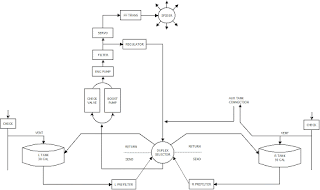
Cool! The same and/or equivalent parts for less than $300... I like it. So that's it, you say? Well, almost. There is one more thing to consider. Now that we have a standalone regulator, what if we move it to the head of the line and "tee" it off the entry to the fuel injection servo? This way, we eliminate any potential over-pressurization issues along the whole fuel system, and we now have the ability to run cooler fuel all the way to the servo. This should pretty much eliminate any hot-start issues and/or occurrences of vapor lock. This isn't a wild or crazy idea of mine, either... it's been the standard for how automotive fuel injection systems have worked for at least the past 30 years (which is of course about 40 years *after* these Lycosaurs were designed). So, after all that, I present you with my first draft of the fuel system diagram:

N165MJ Fuel System Design - First Draft

If you've been following along from the previous diagram, you'll see that really not much has changed except for the "duplex" fuel selector, the location of the pressure regulator, and the path of the returned fuel. I'm going to stew on this design for a little while and figure out the number of connectors, tees, fittings, etc etc that will be necessary to make this all work, and go from there. In the meantime, please feel free to comment (or email me) your ideas or opinions on this design! I welcome all feedback.

One other thing left to cover is the aux tank connections, but that is fairly simple in design. My plan there is to have two fittings and an electrical connector hidden somewhere in the R interior side wall that I will connect to a custom ~20gal fuel cell that can be placed in the rear seat floor or baggage compartment. Fuel will be burned from both main tanks as normal, and then when a tank has enough room in it to accomodate the fuel from the cell, an electric transfer pump inside the cell will be activated to refill the selected tank (either right or left) through the return line. It should work pretty slick... or at least that's the hope.

Whew! Sorry for such a long post tonight. Hopefully I've been able to document my current thoughts in a clear way. Excited to see how this all plays out!



Sunday, August 30, 2015

Section 35 Complete!

Knocked off another section this weekend! By far the hardest part about this section was installing the rear floor pans, discussed in a previous post. The rest of it is really for the most part final-drilling a bunch of #19 holes, dimpling a bunch of #8 screw holes, and maybe the occasional nutplate installation. Easy peasy. Of course, this section isn't really ever "complete" until every last panel has been upholstered/painted and then screwed into position, but that's not necessarily going to happen until the plane is ready to fly-- certainly not until a number of other systems have been installed like the flight controls, brake lines, fuel lines, and wiring. So, I'm calling this section "complete" but really there's just a pile of bare aluminum panels that still need to be painted or upholstered. That will come in time!

Some of the access panels in place (shown unprimed)

It's hard to get the whole bird in the photo nowadays... not a bad problem!

Oh! I almost forgot. Spent a good amount of time this morning modifying the oil cooler mount that I had added to the fuselage kit. Because my engine has the piston cooling oil nozzles, oil cooling needs to perform better than similar engines without this feature (with the positive tradeoff of lower and more stable engine temperatures overall, of course... at least that's the theory). Due to this, I will be using a one-upsize oil cooler, the Airflow performance 2008X. This cooler is the same width and thickness as the stock one, but is about 1-5/8" longer. The mount, then, will need to be modified to accept this larger unit.

The stock VA-186 Oil Cooler Mount

Spacer brackets fabricated to extend the cooler's length

Modified VA-186 mount to accept Airflow 2008X Oil Cooler

EDIT 11/1/2015: I think I may have messed up. Now that the finish kit is here, I think the engine mount will actually be in the way of the larger oil cooler. I may have to redesign this thing from scratch, we'll see. Keep looking for updates on this.

In theory, it's not a very difficult modification. However, it ended up taking about 4 hours to get it just right. Basically, I separated the top plate of the mount from the rest of the assembly and fabricated a few spacer extensions to lengthen the open area for the cooler.. By changing the angles that the cooler originally sat at by a small degree, it retains the same footprint on the firewall and now accepts the larger oil cooler. Cool!

Speaking of cool, we've arrived at kind of a "cool" pivotal spot in the build. Most of the metalwork is done, at least as far as the primary structure of the airframe is concerned. Of course we have by no means set our last rivet, but everything from here on out is really pretty minor as far as aluminum work goes. From here onward, the majority of tasks are going to be centered around plumbing, wiring, control systems, and of course FIBERGLASS. As with many builders before us who have gotten to this stage, we've sorta procrastinated on some of the smaller glass tasks that have presented themselves along the way, and now have a stack of small bits to make as well as a couple large ones. I've heard from many builders that the canopy top and doors are some of the most time-consuming and painstaking parts of the build, and make up for a substantial portion of the total build time.

Also, it's time to start buying "stuff." Everything from wiring, stick grips, fuel lines, brake lines, the rudder pedal system, custom tidbits/upgrades, antennas, lighting, upholstery, and even the beginnings of some avionics. This is both exciting and depressing, as it is going to require careful management of monthly expenses and planning out the logistics of what needs to be bought and when. The UPS guy, if he doesn't already, is going to start to remember this house over the next few months! Who am I kidding, he's gotta already know us :-)

Over the next few days, I'll be assembling a list of things left to do before the finish kit arrives (don't worry, there is still PLENTY to do, I just need to make a list and organize/prioritize). Among the next things to do: (1) measure custom lengths for brake/fuel lines and decide if we're using flex or solid lines, probably a combo of both; (2) paint the interior; (3) continue with the baggage door after my latch arrives; and (4) begin fiberglass work.

Until the list is complete though, marathon-nights of extreme building may be replaced by marathon-nights of extreme reflection on what to do next and how to do it. The metamorphosis from builder to philosopher begins....


Thursday, August 27, 2015

Section 35 Begin

Started Section 35 - Access Covers and Floor Panels today. The first thing they have you do is prep and rivet the rear floor pans into place. I got all the holes drilled, deburred, dimpled, scuffed, and primed in fairly short order. Riveted a few nutplates to the bottom side and thought things are going quite nicely so far, all that's left now is to drop them into place and rivet them down! I must say, this part of the plans caught me by surprise how difficult it was. In my mind, I thought "it's a bunch of blind rivets, should take 10 minutes" but in reality there are a number of solid rivets all around the perimeter, you have to match-drill into the center section spar, and worst of all the panel itself is *extremely* difficult to wedge into position.

The floor panel has three cutouts along the forward side that are supposed to go around the seat brackets and the middle reinforcing hat channel attached to the spar. Well, on mine (and others I've read about) the cutouts were just a tad too narrow to fit around the seat brackets, and this makes installing the floor impossible. It's not evident right away that this is the problem unless you're specifically looking for that, and that's what makes it tricky. Instead, you'll just want to push harder and harder until SNAP something gives. Usually it's the flange on the side of the panel that will buckle. If you're lucky (like I was) it didn't crack, it just bent a bit and I could straighten it back out.

Well, after salvaging my screwup on the L floor panel and getting it all riveted into place, I thought I'd be a hero and take a million photos of the method I thought I had "perfected" now for the R floor panel to show others "the way"... here's what I came up with:

Fiberfrax insulation laid out, and two scrap sheets of thin aluminum to help the panel slide past the seat belt brackets and rivet heads

Panel laid into place with the aluminum sheets on the side helping it slide down


Check for appropriate clearance around the seat brackets

Take an automotive panel/upholstery pry tool to help wedge the panel from the backside

Now just pry it forward to clear the rear spar center section, give her a little push, and....


OWWWWEEE.

Oh for crying out loud! It was going so perfectly too. Just a bit too much pressure in the wrong spot and the damn thing buckled again... this time causing my hand to slip and go right into the sharp, unfinished corner of the aluminum sheet I had so proudly put in place to guide the panel down. So much for a flawless install procedure.

The buckle in the floor panel. Again like the L side, it didn't tear or crack thankfully and could be straightened out by careful and judicious use of the flush rivet set on the 3x gun.

So, in all reality it wasn't the worst situation in the world to be in. Got my hand all patched up (yes that's electrical tape holding the band-aid in place), stuck in a bunch of clecos and straightened out the buckle. In a few hours' time I had both panels fully riveted into place, and a very sore back from sitting in a number of incredibly awkward positions:

L floor pan after riveting


R floor pan after riveting - buckle is erased thankfully!

Whew! Glad that bit is over. Note to future builders: good luck! These floor panels stink. But, when they're done, you have a nearly complete floor in your entire airplane.. yay!

Tomorrow if there's time we'll probably rivet down the rest of the back seat panels (they were left up to provide access to riveting the aft edge of these floor pans) and continue with Section 35!


Wednesday, August 26, 2015

Section 33 Complete!

Well... sort of complete, anyway. Today I worked on the second half of Section 33, which dealt with installing a cover panel on the R side of the baggage compartment (opposite from the door) and drilling/deburring/dimpling holes for the baggage bulkhead corrugation panel. I say "sort of" complete because there are a couple parts that I will be leaving uninstalled for now, namely the R side cover panel because I want to make another conduit run behind it to put wires that I want to keep separate from the other two "main" looms. I had ordered some 3/4" conduit from cableorganizer but for whatever reason it's been delayed an extra couple weeks.

Guess it's a good time to vent about cableorganizer.com. It's been a bit frustrating dealing with them, so far they are my least favorite vendor I've dealt with on this build. They charged/re-charged/refunded my credit card a number of times for some reason which triggered a fraud alert that I had to deal with. When I originally placed my order, everything was said to be in stock, but suddenly one item (zip ties) mysteriously changed to a ship date of 8/31. No big deal. The 3/4" conduit in question though was marked as shipped with the rest of the order on 8/19 (which by the way was 6 days/4 business after the order was placed), however it wasn't in any of the boxes that arrived. When I called to inquire, I was told it wouldn't ship until 8/31, along with the zip ties. This was *not* what was clearly printed on the invoice and all order tracking notifications I received. Grr. Maybe I'm just used to places like amazon and aircraft spruce that ship within a day or so, and seem to be much more "on top of it". Or maybe I'm just bitter about spending over $250 on plastic tubing and zip ties... :-/

Anyway...... first-world problems I guess. The rest of Section 33 went pretty well, and I now have a number of nutplates installed around the perimeter of the F-1006 bulkhead and down the F-1028 channel.

Drilling the #19 holes around the F-1006 bulkhead

Panels removed and nutplates installed!

In the pic above, you may notice that the F-1031 Upper baggage door seal channel is not yet installed. I'm also leaving this part out for now until I figure out exactly what I'm doing for the baggage door latch. I'm not crazy about the idea of the standard key-only latch mechanism; I'd rather have the ability to lock-unlock it and then have some kind of paddle handle or slide latch to open and close the door. I'm searching far and wide for the "perfect" latch and it's been kind of hard to find so far. I'll keep searching, and I don't think that will really keep anything else from continuing in the meantime.

I also finally installed nutplates along the forward tunnel along the top edge. Technically this was supposed to be done a while ago (I think in the firewall section?!) but I kept procrastinating, knowing that it could be done at basically any time since there is easy access to that area. No worries, that's done now too.

So, all that's really left to do with Section 33 is final-installing the F-1080 baggage cover once I finally get my conduit, and final-installing the F-1031 baggage door channel once I figure out what my baggage door latch is going to be. Oh, and installing the rear seat belt wear blocks, but again I want to hold off on that until I actually have my restraint system purchased and in-hand. Three quick and simple tasks... good enough for me to call 33 done!

Next up, I'm going to skip 34 (baggage door) for the same reason as above until I find the right latch, and going to start on 35, Access Covers and Floor Panels. Should be a fun section, hopefully!

Tuesday, August 25, 2015

Baggage/Rear Seat Floors

Productive day today! Primed all of the parts needed to complete the first half of section 33 over lunch and then got to work laying insulation and riveting the floors into place! Similar to the forward floors, I used a layer of 1/8" Fiberfrax insulation, and topped it with Ultratouch under the rear seats only. Under the baggage area, I used aluminum tape to secure the relatively thin and light Fiberfrax.

Insulation laid up, ready to install floors!

I started riveting the floors on and realized my pneumatic rivet gun wasn't working right. It started taking two, and then three squeezes to actually set the rivet, which got old quick. I thought maybe the gun was starting to wear out or something, but it turned out to be part of the internal mechanism had started to unscrew from itself and was limiting its range of motion. We had disassembled the gun months ago to clean all the proseal out of it, and I think we must not have tightened everything back up fully. Whew! That was an easy fix, I was hoping I wasn't going to have to end up buying another gun or something. Anyway, after a night of riveting here's what we ended up with:

L baggage floor and baggage door opening, from inside

Baggage door opening, looking inside toward floors

All sealed up!

Baggage floors


We're now through Section 33-7 Step 5... yay! The second half of this section will now build on this and install a cover panel on the R side of the baggage area, and match-drill and install nutplates to hold the Baggage Bulkhead Corrugation panels.

The end of Section 33 is in sight!!!


Monday, August 24, 2015

Steps and Aft Flooring

Time for some pics! Final-installed the steps and ran wiring conduit today, bringing us one step closer to being ready to rivet on the aft floors. I started this by modifying the TCW Step Bushings I ordered to facilitate installation. The plans they come with suggest to use a rope or strap to "drop" the bushings into place, but I had an idea to tap a 3/8" threaded hole in the middle of the bushing so that it could be attached to the end of a threaded rod, allowing push/pull force to be applied as the bushing is inserted. It will also make future removal of the bushing possible, should that be needed.

Drilled 5/16" hole and beveled

Tapped 3/8-16!

With the bushings tapped and attached to the rod, it kinda looked like an industrial-grade marshmallow on a stick! Except not as delicious. Anyway, I also ended up re-drilling the holes through the steps so that the bolt slides in horizontally instead of vertically, so that they can be removed with the floors in place. I also upgraded to an AN4-20A bolt instead of the default AN3 size. After a quick drilling, deburring, and priming session, the steps made their way into their final spot and got bolted into place. Looking at the empty original hole on top of the mounting collar, I then realized I could take a small AN3-5A bolt and carefully drill/tap it into the bushing from the top side, giving an extra degree of shear strength too. This small bolt will still be removable from the bottom should the need ever arise.

L Step final-installed-- Silver powdercoat looks slick!

R Step from the inside


AN4-20A bolt horizontally through the whole tube with washer/nut on other side, and an AN3-5A bolt on top, tapped into the bushing and secured with blue threadlock. Where's this step going? Nowhere!

After that, I ran some 1" conduit through the baggage and rear seat areas, one on each side. The conduit fit quite nicely through the holes I had drilled, and I reinforced the tube at each passthrough with a few layers of Super33+ electrical tape, and secured with a zip tie. Should hold up very well!

Conduit runs through each side

Conduit runs through each side. Oh yeah, there's my modified battery tray too! :-)

Zip tie over Super33+ tape securing tube in place at each passthrough

That was pretty much it for today! I still need to prime the aft floor parts, will hopefully get to that tomorrow. Then all that's left to do is insulate under the seats and start putting it all together!


Sunday, August 23, 2015

Section 30-something Randomness

Haven't posted an update in almost a week! Oops. It's been a weird few days... not that we haven't been working on the plane, but we haven't really made much visible or reportable progress on any one thing.

We'll cough up the non-building excuses first: Thursday last week we flew the Archer from KIIB up to KMCW for a "Third Thursday" cookout and met up with our friend Martin in his Bonanza. Had a great time up there as usual and then flew down to Marion to hangar the plane near home for the weekend. I've been working off-and-on on a side-project for my dad also that's been taking some time. Yesterday morning I participated in my first Young Eagles event as part of our local EAA chapter hosting an airport staff/friends/family event at KCID. There wasn't a huge turnout, only maybe a dozen families at most for 10 planes, so I only took one passenger load-- a mom and her ~11 year old daughter. The mom seemed to have fun but unfortunately the little girl didn't enjoy her first ride in a plane as much as I had hoped she would. It was a bit bumpy out that morning, and some of the gusts even caught me by surprise a bit. So, after a quick shot over downtown Cedar Rapids we made a quick dash back to the airport with a teary-eyed girl in the backseat :-( Oh well, at least no one got sick... Hopefully the next event will yield more visitors, smoother air, happier passengers, and inspire some future pilots!

On the days in between all that though, some decent progress was made. I deburred and dimpled all the parts that Derek and I prepped last Tuesday. I rebuilt my "tailwheel" to be a bit more robust and have the tail sit a bit higher so the fuselage is more level. I've begun work on my instrument panel to try and figure out what is going to go where. So far, here's my plan for the panel. Aside from some lights and switches, there will be four "big ticket" items on the panel itself: A dual-screen 10" G3X Touch system, GMC307 control panel, and GRT Mini-X as a backup EFIS. On the lower center console, I'll put my audio panel and navigators, possibly one or two GNS430W's, or an SL30... or if I win the lottery a GTN750/650 stack. We'll see. It's sort of depressing how expensive this stuff is. Even obsolete units are many thousands of dollars. Never thought that "going cheap" still meant spending $20k! Ha. Regardless for what I end up with though, there should be room for any of the above, so we're good there.

In addition to the above, I also made cutouts in the fuse bottom skins under the steps for some access panels. I realize most people put access covers in the baggage floor on the inside and not on the outside, but I wanted to do this a bit differently and also equip the cover with puddle lights to illuminate below the steps. Hopefully that all goes to plan. My Panduit solid corrugated tubing arrived from CableOrganizer.com. I'll be running two 1" tubes from aft of the baggage area to forward of the rear seats, past the new access holes and the steps. Speaking of the steps, I got them back from the powdercoaters, they look awesome! I also received my TCW Step Bushings in the mail, so I think we're getting pretty close to buttoning up the first half of Section 33 (the second half requires you to have the rear seat and baggage floor panels installed... which requires steps to be installed and wiring conduits run).

Lastly, I've started dabbling all over the plans, working on section [mumbles]30-something. Started on the baggage door. Started planning for the fuel and brake lines, location of the parking brake valve and fuel selector valve, and tallying all the lines and fittings that need to be made. Pestered Paul Grimstad at Control Approach one more time about his rudder pedal system. He's working frantically on getting a prototype completed and will be ready to ship "soon". I've got plenty to work on before I "need" them for sure but I'd like to get them here sooner rather than later if possible. Started on the access covers and floor panels section, particularly for the tunnel cover. Got a few random parts in the mail including a clear brake reservoir (Matco) and a ground power connector (Cessna-style).

All of this feels like I'm going in 100 different directions and nothing is complete yet. There are a lot of inter-dependencies on things being complete before work can start on the next thing, etc etc. Hopefully a lot of that will get sorted out in the coming week. Until then... maybe we'll have some pics and noteworthy progress in our next installment!


Tuesday, August 18, 2015

Upper Forward Fuse - Baggage Area

Yesterday I had a brief session in the factory to remake the F-1044B angle that I had mis-drilled last time. I actually ended up doing this twice, because I messed up my first remake. Third try was the charm though, and so now in addition to the usable part I have two 17-5/16" long pieces of aluminum angle that I'm 100% certain will get put to good use on some future part of the plans. Not ideal, but oh well that's the way it goes sometimes. At least I didn't have to reorder any parts I suppose.

One other bit of news from yesterday, I called Van's to place my order for the finish kit! They are quoting an 8-week lead time, and although I'm pretty sure I won't be *done* with the fuselage in 8 weeks, it will be nice to have some of the parts contained in that kit a little ahead of time. I have a few weeks now to finalize a "delete" list and send in to them. I'll cover this in a future post.

In the meantime though, tonight it was time to start on the task of deburring all the upper forward fuse parts. It actually went pretty quick using the EZ-Burrs on all the drilled holes and the belt sander for all corners and edges. I started dimpling a few of the smaller parts, but got bored of it and started thinking about how I won't really be able to get too much further with all these parts until I figure out my panel layout a little better. So, I tossed the pile of parts back into the shelf and will continue with that as we get closer to section 41 where it all actually has to be attached permanently (Section 31 is sort of designed to be an "at your own pace" section and allows you to slowly put your panel together outside of the airframe and then attach the whole works in section 41).

Shifting gears to Section 33 then (remember 32 is tailcone attach, complete!), we began work on the rear seat and baggage floor areas. I won't be able to final-install the floors yet before we get the steps back from powdercoating and I finalize my antenna layout, putting any necessary doublers under the back seats... but that won't stop us from prepping all the parts!

Derek came over tonight to help out, and we had a mega-productive session match- and final- drilling the floor covers. We started off with the back seat floors and moved aft to the baggage floors per the plans, which included cutting some AN257-P3 hinges to size and match-drilling them to the panels. The hinges will be used to attach the rear seatbacks to the airplane, and allow for removal by simply pulling the pins out. I took charge of the L side of the airplane, and Derek took the R side (Sarah took a "supervisory" role tonight). With two drills and two cleco pliers going, we made quick work of it all!

The back seat floor covers after match-drilling

The L baggage floor cover with hinge clecoed into place

Derek match-drilling the hinge to the R baggage floor cover


We finished the night off by making the F-1022 B-G stiffeners and final-drilling them to the R and L baggage floor skins. Derek did an awesome job cutting all 12 pieces from the two provided long aluminum angles using the bandsaw and belt sander to clean them up! While he was doing that, I went ahead and deburred all #30 holes in the four floor panels, leaving only the #40 and #19 holes to finish up.

Great night of productivity! It really feels like things are kicking into high gear, and I can't wait for this thing to be ready to fly!! Gotta keep my excitement in check though, still got quite a ways to go... it's hard to imagine that we're really only about halfway done at this point... probably not even half!

Sunday, August 16, 2015

Center Console

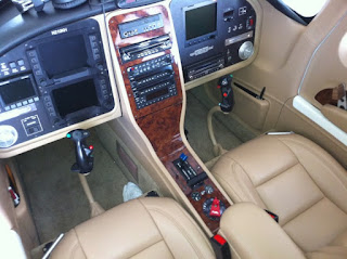
Today I started on a rough-cut of a home-brew center console I want to make. Instead of putting the throttle/prop/mixture controls up on the panel like many RV's, I want to put mine down on the tunnel, closer to the armrest, and then use the center console area for a radio stack, switches, etc. The general idea came from a photo I saw of Greg Hale's famous (perhaps infamous) RV-10, N210KH:

Greg Hale's RV-10

Say what you want about some of the other modifications he made to this aircraft, but the interior is stunning. Van himself wrote a fairly scathing review of this airplane, visible here (link). I actually spoke to Van at Oshkosh this year and thanked him for writing that article, because I believe it has helped me resist many of the temptations that are out there to go balls-to-the-wall with modifications and not realize the safety implications of changing major parts of the design. I highly recommend reading that article if you haven't already. Anyway.... back to the interior and center console, which has steered clear of that sort of scrutiny. Although I'm not personally a fan of the color or wood grain trim, and I'll have a slightly different avionics configuration, I do like the general form and layout of this panel, and will use this as an inspiration for my own less-fancy design. Off to the workbench to further my metal-forming skills!

The tunnel cover is about 5.5" wide and 10.5" down underneath the front of the panel and slowly expands to 6.5" wide about a foot further forward under the panel. The sides of this center console need to be at least 6.3" wide in order to fit a radio stack. So, I took two pieces of 0.032" aluminum sheet and made matching conical bends (basically a mini-version of what was done to the mid fuse skins) to attach to the tunnel covers, and then bent them outwards at the top to "flow" into the panel. I made a temporary jig out of hardware-store aluminum angle to keep both pieces square and straight and clecoed it all into place:

Rough-cut of the center console

Looks good so far! Well, it looks "ok" so far. Good from 10 feet, but still have quite a bit of trimming and tweaking. For the most part it is square and centered, and at a 6.5" width it should accommodate a radio stack quite well. The filler pieces inside there are only temporary as described above, and ultimately it will just be a 6.5" x ~10.5" cavity to flush-mount my GPS's (i.e. GTN650 etc). Covered with upholstery and everything, it should look pretty slick. I hope, anyway.

That's pretty much it for today! As any builder will say, once you start going off the plans to make stuff like this, it takes 10x as long. Tomorrow I'll probably get around to fixing yesterday's goof with the F-1044 angle, and maybe start on the baggage compartment section!


Saturday, August 15, 2015

Tailcone Attach - Cradle - Upper Fwd Fuse - Section 32 Complete!

Today was one of those "builder's dream" productivity days! It actually started last night when I finished a few of the rivets that I could reach myself for the tailcone attach. I was actually able to reach almost all of the rivets on both sides and that attach the ribs and bulkheads, but still needed Sarah's help to finish the ones along the bottom. While I waited for that, I figured it was time to get the fuselage off of my work tables and set it on the ground in its own cradle. I set out to build those, and what I ended up with is pretty close to other ones I've seen online:

She's on her own feet for the first time! (albeit with temporary shoes... err maybe wooden clogs)

Presenting the RV-10 taildragger!

The front legs are basically just 16" long 2x6's with holes match-drilled for one big and one small hole in the center section bulkhead. Basically working from inboard to outboard, the holes go "SBBS": I have one small and one big wing attach bolt in positions #1 and #3, and then these 2x6's are attached at positions #2 and #4. I had to scoop out little reliefs on the inside faces of the 2x6's to make room for the  wing attach bolt heads, which took a bit of time and head-scratching, but I eventually prevailed using a bit I had laying around from when I made my computer desk in the drill press: the kind of bit you use to install recessed hinges in cabinet doors.

Hardware-wise, I used 4x 1/2" x 8" bolts in the "big" holes and 4x 5/16" x 8" bolts in the "small" holes. I had originally bought 3/8" bolts for the small holes, but silly me, they were too big. In the photos above, I hadn't yet made the exchange so you only see the big bolts in place.

For the tail wheel, I padded some 2x6's to hug the end of the tailcone, and ran a single 3/8" bolt up into the tie down hole, tightened only to be "snug". It worked but it wasn't super stable if you put a lot of weight in the tail, so I ended up rigging a little 2x4 arm to come forward and rest against the bottom skin a foot or two ahead of the attach point. The arm is held tight against the bottom skin with a tiedown strap. A little ghetto but hey it works. And there you have it!

At about this time, Sarah came out and we finished riveting the bottom rivets between the tailcone and fuselage. That puts an end to Section 32... yay! I'm liking these few-day-long sections as opposed to the few-week-long sections like 29. :-)

Next on the agenda was the Upper Forward Fuse assembly, Section 31. This section is relatively straightforward and starts off like many of the other sections fabricating some small aluminum pieces for who-knows-what and then as you start to cleco things together it all starts to make sense. I snapped a photo of the first step:

The F-1044C Spacer - And my feet.

Interestingly, this piece that I fabricated played a co-starring role in a minor goof-up I had today. As you begin to assemble the different pieces, there was one kind of odd thing they have you do, which is to match-drill the F-1044B angle into a brace on the firewall by drilling "up" through the firewall recess (they first have you drill a pilot hole "down" from the brace through the recess). Kind of an interesting process. Anyway, the goof-up was that I forgot to put the F-1044C spacer that I had just so proudly fabricated into place, so the hole drilled through the F-1044B angle isn't in the correct location. Oops! I'll have to toss the piece and make another one. Oh well, should be a zero-sum game in the end, I have plenty of extra aluminum angle sitting around. For now, I decided to continue with assembling the rest of the assembly for match- and final- drilling:

The "subpanel" and three ribs clecoed to the forward fuselage. The errant F-1044B angle (accidentally sans F-1044C spacer) is visible attached to the middle rib.

For a while, I thought this F-1044A center rib might have been formed incorrectly at the factory-- the holes in the forward flange are much closer to the web than normal and were a PITA to dimple. They are correct though!

Right side of subpanel

Forward top skin clecoed into place for final-drilling!

This makes the airplane instantly look super-neat (as if it's not already super neat-looking, anyway). It's easy to get lost just staring at the thing and watching the time go by. However, I resisted that temptation and proceeded with all the necessary drilling tasks. The focus then shifted to the inside of the cockpit now, where the last drilling task remained: match-drilling the F-1003D/E flanges. These pieces start life as 0.032" aluminum angles and must be fluted to match the contour of the top skin, ensuring that no flutes are made where the instrument panel attach holes are. This proved a bit tricky but in the end wasn't all that bad. After that though, you have to hold the pieces up under the panel and match-drill down (towards your fingers!) into the angle. It was a bit of a sticky situation but ultimately I only had one "close encounter" with a drill bit poking through, and no blood was shed during that battle. Whew!

That's pretty much it for tonight! Tomorrow I think I'll start on an idea I have for a center console to go between the panel and tunnel... stay tuned!


Thursday, August 13, 2015

Tailcone Attach - Static Ports

The tailcone attach section is going a lot more quickly than I thought it would! Finished final- and match-drilling the various parts between the fuselage and tail section, and before long the two halves were separated again for deburring, dimpling and countersinking. There were a small handful of parts that needed priming, including some parts around the baggage door, both mid fuse longerons (I had previously left them only clecoed into place until this section could be completed) and the F-1006 bulkhead parts which I didn't prime or rivet together during the empennage construction to simplify things a bit.

While the primer was drying, I wanted to finish one relatively small task that would be much easier to complete now before the tail gets attached-- installing the static ports. I've decided to go with the SafeAir static ports and plumbing lines, which I've had on hand for some time now but haven't done anything with. Looking through the instructions, installing the ports appeared to be a lot easier than I was thinking it was going to be. You have to enlarge the small pilot hole in the tailcone side skins to 1/4" in diameter and then mount the static ports from behind. The port, with its angle attachment and adapter for air hose, looks like this:

SafeAir static port with 90-degree air hose fitting
(photo stolen from online, I forgot to snap a picture of mine prior to installation)

To actually mount the port, you have a few options. Many builders choose to rivet the ports into place, which would be fine except I'm not a huge fan of dimpling the middle of a large piece of skin once it's already been installed. It can be done, but it's time-consuming, nerve-wracking, and never seems to produce the same quality dimples you can do on the bench. The second option is to adhere the part from the back with proseal or some other adhesive. I chose this route and actually just used standard epoxy resin to install these.

I first traced a circle on the inside of the skin to mark where the port will actually mount, and then removed the primer on the skin from this area using a dremel with wire wheel brush. Cleaned the area up a bit with some acetone (carefully!) and then scuffed up the face of the port with some sandpaper, making certain to not scuff up the actual "nipple" on the port itself. Cleaned both surfaces again, this time with alcohol, let it dry quickly and applied the epoxy to the static ports, again making sure to keep it away from the nipple. Then I stuck them into place and held firm with some masking tape. Hopping out of the cone to the outside, I then cleaned up any excess adhesive with alcohol. After the epoxy cured, I installed a tee fitting into an existing hole in the bulkhead and ran the air lines to it. The result came out pretty good!

The static air port after installation

Inside view of static system ports and air lines... ready to run to my ADAHRS!

Once this was done, I riveted the Mid-Fuse longerons into place which was maybe a couple dozen rivets per side and didn't take too terribly long. Then the "momentous moment" was upon us: mate the fuselage and tailcone for good!

The last time we see the tailcone by itself

Riveted the F-1006 bulkhead to the tailcone (this is the opposite from the previous time they were joined, where you cleco this bulkhead to the fuselage)

Final moments before joining

Joined!

Now, just a few dozen (ok, maybe a hundred or so) rivets and this thing is permanently attached... nice!!! That's it for now, I'll save the fun and rewarding task of riveting for another day...