Primed all of the leading edge skeleton parts, as well as deburred, dimpled and scuffed the L leading edge skin. Struggled a bit managing the awkward curved skin around the dimpler but eventually got it all dimpled without any dings. Also continued riveting the top skin, finished bucking all rivets that couldn't be gotten with the backrivet set, as well as all the rivets along the main spar on the L wing. Still need to do the main spar on the R wing, as well as both rear spars. Wow this is a lot of rivets!
No pics today since everything still looks pretty much the same. I promise I'll take some pics tomorrow :-)
Monday, March 23, 2015
Sunday, March 22, 2015
Wings
Another full day of (non)exciting work on the wing! Spent most of the morning and afternoon deburring, scuffing, and dimpling ALL the leading edge parts for both sides. The plans call for you to only final-drill the spar-to-nose rib holes as it is being installed, but I figured it might be better to do that drilling now before priming and assembly of the leading edge. Plus, we wanted to see what the nose ribs look like when attached to the wing :-)


L nose ribs clecoed to the main spar
R nose ribs clecoed to the main spar
First time we really get to see the airfoil shape of the wing!
We finished the day off by continuing with some top skin riveting. In a burst of motivation and productivity, we got ALL of the rivets that could be back-riveted done for both wings! We also installed the rivets and nutplates on the inboard side of each wing. Now all we have to do is go back over the skins with the conventional flush rivet set and bucking bar and complete the remaining ~200 or so rivets. Exciting times!
Still to-do list for top skins and leading edges:
- Finish bucking top skin rivets that could not be back-riveted.
- Deburr and dimple the leading edge skins
- Prime leading edge parts and skins
- Assemble leading edges
- Install leading edges to wing
Saturday, March 21, 2015
Wings
Sarah had to work today and has some family plans later on, so I decided to continue with the leading edges myself, and then I think tomorrow we'll finally get around to continuing/finishing the top skins.
First, the brackets for the landing lights had to be fabricated. An annoying thing about the Duckworks kit that I discovered was that because I got the lampless kit, I didn't get any instructions other than the two templates (skin and rib) and a very rough sketch that shows how it's all supposed to go together. No big deal, but it required figuring out which rivets were for what, and where the nutplates go, etc etc. Also, the baggie that they sent containing all the rivets and fasteners also had a small roll of double-sided tape in it, which stuck to all of the parts inside, resulting in a sticky, goopy ball of rivets and nutplates that was very difficult to separate and clean off.
In order to figure out how to proceed with fabricating the bracket, I relied heavily on Tim Olson's writeup on his site (link here) which helped a ton... thanks Tim! Unfortunately, I don't have any pictures of the fabrication process, but I ended up with a very similar-looking piece to what can be found on his site with the same overall length of 15-1/2" (the distance between the two outboard-most ribs). The only difference is that my cutout in the bracket for the landing light will fit my 40W LED spotlight instead of Tim's HID setup. I'll take some pics and post them once it's assembled again. It did come out pretty nicely, and I'm excited to see it all installed and working!
Once the bracket was made for the L side, I duplicated the fabrication process to make a mirror image bracket for the R side. Then, I started the prep work on the R leading edge by assembling the ribs, splice strip and J-channel into the skin. Final-drilled all the holes, and cut out the hole in the leading edge for the landing light. Of course, this side does not have a stall warning system, but I am electing to install an access hatch on this side too, just in case we ever need to get in there for some reason.
Unbelievably, there are zero pictures from anything at all today! Sorry about that, it was a lot of heads-down work on the landing lights and then more of the same kind of stuff that had already been documented for the L wing, replicated on the R side.
First, the brackets for the landing lights had to be fabricated. An annoying thing about the Duckworks kit that I discovered was that because I got the lampless kit, I didn't get any instructions other than the two templates (skin and rib) and a very rough sketch that shows how it's all supposed to go together. No big deal, but it required figuring out which rivets were for what, and where the nutplates go, etc etc. Also, the baggie that they sent containing all the rivets and fasteners also had a small roll of double-sided tape in it, which stuck to all of the parts inside, resulting in a sticky, goopy ball of rivets and nutplates that was very difficult to separate and clean off.
In order to figure out how to proceed with fabricating the bracket, I relied heavily on Tim Olson's writeup on his site (link here) which helped a ton... thanks Tim! Unfortunately, I don't have any pictures of the fabrication process, but I ended up with a very similar-looking piece to what can be found on his site with the same overall length of 15-1/2" (the distance between the two outboard-most ribs). The only difference is that my cutout in the bracket for the landing light will fit my 40W LED spotlight instead of Tim's HID setup. I'll take some pics and post them once it's assembled again. It did come out pretty nicely, and I'm excited to see it all installed and working!
Once the bracket was made for the L side, I duplicated the fabrication process to make a mirror image bracket for the R side. Then, I started the prep work on the R leading edge by assembling the ribs, splice strip and J-channel into the skin. Final-drilled all the holes, and cut out the hole in the leading edge for the landing light. Of course, this side does not have a stall warning system, but I am electing to install an access hatch on this side too, just in case we ever need to get in there for some reason.
Unbelievably, there are zero pictures from anything at all today! Sorry about that, it was a lot of heads-down work on the landing lights and then more of the same kind of stuff that had already been documented for the L wing, replicated on the R side.
Friday, March 20, 2015
Wings
Burned some midnight oil tonight. Instead of doing any more wing top skin work, I continued with the prep-work for the landing lights and stall warning system in the L leading edge. First thing was to cut out the hole for the light. Before receiving the kit, I had searched online for the exact dimensions of the cutout and couldn't find anything, so I snapped a photo of this:


The Duckworks RV-10 template laid over the L leading edge, outboard bay. The light can be installed in any bay, but most people opt for the outboard-most bay for a number of reasons, so I'll follow along.
The hole is 5" wide, 2-1/2" in from the rivet line. It begins about 19-1/8" from the aft edge on top, and 15-7/8" from the aft edge on the bottom. Corners are radiused approximately 1-1/4".
Here's my take on cutting out the hole: I've read a number of build blogs that talked about how scared they were to cut the hole, and then it turned out to be pretty easy. So I guess I went into this thinking no big deal, it will be really easy and take 2 seconds. Well, I guess I struggled with it more than I was thinking I would, because I ended up using a ton of different tools to get it cut out. I used a body saw, an air nibbler, a cut-off wheel, a dremel, a drill-powered sanding drum, and a hand file. No single tool was fit for the entire job, but the combination of them all seemed to do the trick. Finally though, I prevailed, without any dreaded slips or ugly nicks:
The L wing cutout for the landing light
Since I had all the cutting tools out, why not do the stall warning system too? Skipped ahead to Section 20 and began prep work for that.
Access hatch cut into L leading edge skin, inboard-most bay
Stall warning flapper cutout. This works similar to many production aircraft, with a metal tab that sticks out of the leading edge and actuates a micro switch to sound the stall alarm.
Funny sidenote about the stall flapper cutout in the leading edge: RTFI (read the instructions)! The skins come pre-punched with two very small (~3/32") holes to mark where this cutout needs to go. Step 19-2.15 says to file out the area between these holes to make the cutout. However, I missed reading the previous step 19-2.14 where it says to enlarge the holes to #10 first! So, I spent like 30 minutes with the world's smallest file, making a perfect 3/32" slit in the leading edge, thinking "man, this thing is TINY." Had to laugh at myself once it was done and how long I spent making a slit that would have to be enlarged later. Oh well.
The micro switch and components provided in the kit for the stall warning system
Thursday, March 19, 2015
Wings
In a burst of motivation, we got all the way through the R wing top skin rivets that could be back-riveted! This excludes rivets along the front and rear spars, as well as the aft 3 rivets on each rib, since the rivet set doesn't sit straight on the rivets. We can either buy a double-offset back-rivet set, or just buck them normally. I think we'll just do that, unless it turns out to not work very well. So far the top skins are coming out pretty darn straight, I'd like to keep it that way if we can! We're bound to ding some part at some time though, I'm sure :-)


"Most" R top skin rivets complete! Sarah is happy :-)
R top skin, inboard looking out
Now we'll have to finish those hard-to-get rivets with a bucking bar and get going on the L wing... the end is in sight!
Wednesday, March 18, 2015
Wings
We got off to kind of a slow start back-riveting the top skins, starting with the right side this time. Initially, I thought it would be a good idea to insert a bunch of rivets at and hold them in place with rivet tape, similar to how we've back-riveted other parts... but then by an hour or so into this I realized it would be much easier to just cover the bucking bar with packaging tape and insert rivets one at a time as we went (by the way- this is the method Van's calls out in the plans, I was just being ridiculous and trying a different method). Anyway after an hour or so we hadn't made a ton of progress and we were both bored. This is going to take a while to get all 1000 or so rivets done on both wings. We had gotten this far though:


Day 1 of riveting the R top skins
It's a good start, but we have a LONG way still to go!
So with that, we decided to move on to the next part just for a change of pace. Skipped ahead to Section 17 and started the prep work on the L Leading edge:
The L leading edge clecoed together
Some of the ribs had to be notched out to sizes called out in the plans for clearance from the main spar.
It's a pretty basic part actually, consisting of 7 ribs, one J-channel, a splice strip and the skin. I wanted to get a jump start on it though because there are a few modifications required to install the Duckworks landing light kits we got. So, after some final-drilling we called it a night. Lots more riveting to come!
Tuesday, March 17, 2015
Wings
Excellent progress today catching the R wing up to the L wing! Primed and riveted the R rear spar to the wing. Realized it's way easier to dimple the holes along the top of the spar while it is still off the plane and not assembled, would recommend doing it this way for next time instead of trying to work around all the rivets installed on the spar already. Once the spar was in place then it was time to finish prepping the R wing skins, which didn't take nearly as long as I had thought it would. We're having lots of fun with the new dimpler! The skins were deburred, dimpled and primed within about 2-2.5 hours, which I think is pretty good considering the number of holes. Hung the skins on the wing and now both wings are at the exact same stage: ready for riveting!
Tomorrow should be a "riveting" experience.... (did I already use this joke in the blog before?)


Tomorrow should be a "riveting" experience.... (did I already use this joke in the blog before?)
Both rear spars complete! (inboard)
Both rear spars complete! (outboard)
R top skin (inboard) in place
R top skin (outboard) in place
Monday, March 16, 2015
Wings
Today we finished deburring, scuffing and dimpling the L top skins and then primed everything. The L skins are now clecoed into place and ready to rivet! Instead of riveting though, we continued with the R wing to finish the rear spar and top skin preparation. The R rear spar parts (including the new W-1007D) are all drilled, deburred, scuffed, and ready for primer. The R top skins have all been final-drilled, countersunk, and nutplate attach (inboard side) all prepped. Still need to finish deburring the holes, then scuff, dimple and prime. Once that is complete (hopefully tomorrow) we will be ready to rivet both L and R top skins to the wings!


L outboard top skin after dimpling, ready for primer!
Priming the skins with Rustoleum aluminum primer
The R rear spar parts all drilled, countersunk, deburred, dimpled, and scuffed... ready for primer!
The L top skins in place and ready for riveting
L top skins from the other side
Sunday, March 15, 2015
Wings
Started off this morning not working on the plane directly, but wanted to make some improvements to my dimpling tool. When we started this project, I decided I wanted to make my own C-frame dimpler embedded into the work table. I've seen the commercially available ones, and of course the DRDT-2, but for me I couldn't justify the cost if it didn't do 'exactly' what I wanted. So... I got to work on an idea I had a while back to make the best dimpling device ever. If I failed, I told myself I'd just break down and get a DRDT. To my own surprise, I think I succeeded! Total cost? $0.00! An aviation first! :-)
The idea was to attach an air hammer (or rivet gun) to a swinging arm that could go up and down towards the very edge of the workbench. On the gun would be the male half of a dimple die, and then the other half of the die would be placed into a very heavy steel block, slightly recessed into the work table at the very edge. This way, the dimpler can accommodate very large sheets (i.e. wing skins) and process them very quickly and consistently, since the air hammer will always be held straight and level by the swinging arm. Also, since the lower block is embedded into the edge of the table, it will be perfect for dimpling the leading edge curves using the gun and dimple die by hand.
The dimpler was built using some leftover 1" x 1" square steel stock from the first dimpler, some angle iron, steel plate, hose clamps, and an old air hammer that I've had for a while and still works great. It felt very MacGyver-ish, only I didn't need to use a paper clip or duct tape. The air hammer isn't as "precise" to control as the rivet gun, i.e. there aren't numbers printed on the air control valve but otherwise I still can't tell the difference between the two for the life of me, other than the price (Maybe that's what the "3x" means? ;-)). Anyway the air hammer is perfect for this. I test-ran it on some scrap running the gun at 35-40psi with a 1-second or so burst and the dimples came out 100% perfectly coined! I think if someone wanted to go out and buy all the parts new for this they'd spend less than $50. Here's the completed setup:


The idea was to attach an air hammer (or rivet gun) to a swinging arm that could go up and down towards the very edge of the workbench. On the gun would be the male half of a dimple die, and then the other half of the die would be placed into a very heavy steel block, slightly recessed into the work table at the very edge. This way, the dimpler can accommodate very large sheets (i.e. wing skins) and process them very quickly and consistently, since the air hammer will always be held straight and level by the swinging arm. Also, since the lower block is embedded into the edge of the table, it will be perfect for dimpling the leading edge curves using the gun and dimple die by hand.
The dimpler was built using some leftover 1" x 1" square steel stock from the first dimpler, some angle iron, steel plate, hose clamps, and an old air hammer that I've had for a while and still works great. It felt very MacGyver-ish, only I didn't need to use a paper clip or duct tape. The air hammer isn't as "precise" to control as the rivet gun, i.e. there aren't numbers printed on the air control valve but otherwise I still can't tell the difference between the two for the life of me, other than the price (Maybe that's what the "3x" means? ;-)). Anyway the air hammer is perfect for this. I test-ran it on some scrap running the gun at 35-40psi with a 1-second or so burst and the dimples came out 100% perfectly coined! I think if someone wanted to go out and buy all the parts new for this they'd spend less than $50. Here's the completed setup:
Some steel stock, angle iron, and hose clamps and a couple bolts attach the gun to the swinging arm.
The gun, arm, and attachment to the table. It does have some side-side slop, but as long as you don't really torque on it, it is quite easy to line up with the die. You can also see the patch job I did to cover the previous hole where the old C-frame dimpler was set up. Not the prettiest, but it works.
Straight and level from all angles. I put black carpet over the lower block because it was an ugly mess of steel bars and cut-up 2x4's, this makes it look a lot better.
When you're not using the dimpler, you can swing it up and out of the way. I should probably put some sort of up-lock on it so that it doesnt get bumped and come crashing down. Maybe a spring too. We'll do that in v2.0.
Anyway, on to the actual work for the skins. We final-drilled all the holes in the top skins, and I also countersunk/dimpled the areas of the top skin that needed to be while still on the wing. No pics, since it pretty much looks the same as it did yesterday. Towards the very end of the day, I was able to pull the L top skins back off the wing for the exciting task of deburring/dimpling. I got through the wing walk doublers and the inner skin (the smaller of the two), and decided to call it a night. Good news though, the dimpler works perfectly!
The MikeyJ-2000 dimpler in action on the W-1002 top wing skin!
Dimpled, scuffed, and ready for priming!
And that's all for this weekend, folks! Hopefully this week we'll get through the top skins on both sides and be ready to tackle the leading edge!
Saturday, March 14, 2015
Wings
Some real progress today! Primed, assembled and riveted the rear main spar for the L wing per the plans (15-4 step 4). This involved leaving a line of rivets out along the lower-middle of the spar for later attachment of the gap fairings. Other than that, this completes the skeleton structure of the left wing! In the meantime, Sarah got to work starting Section 15 on the right wing, match-drilling and assembling the 5 pieces of the rear spar. Well, 4 pieces... we're proceeding without the W-1007D/I piece for now until it arrives.



The W-1007B/C spar doubler (most inboard)
The W-1007D/I spar doubler
The W-1007D/O spar doubler with W-1013-L aileron attach bracket
The W-1007E spar doubler
Got some new toys in the mail today too! Got my shipment from Cleaveland tools which included a handheld back-rivet bucking bar and long back-rivet set to use on the wing top skins, Also got a new drill... being a DeWalt guy myself, I've come to realize 90% of the drilling we do does not require a bulky, heavy, powerful drill... small and lightweight is good especially when you have a million tiny holes to drill. So we got a Bosch PS31-2A. Seems to fit the bill perfectly!
The back-rivet bucking bar from Cleaveland Tool. Beefy! Can't wait to give it a try.
The diminutive and lightweight Bosch drill. It works perfectly for the majority of our drilling needs!
The last thing we got in the mail today was a surprise indeed... the W-1007D doubler I had reordered from Van's! I was sure that it would take longer than this to arrive, but this is great news. We'll be able to finish up the rear spar on the right wing now!
After finishing the L rear spar, I got to work on Section 16 for the top skins. This was exciting to me because it's the first skin-related step since working on the tailcone. Also, clecoing skins into place is usually pretty fun and goes quickly, with a dramatic change in appearance:
The two W-1027A/B wing walk doublers fit unto place underneath the top skin
The W-1002 inboard top skin, clecoed in place over the doublers (also Sarah final-drilling the rear spar on the R wing)
The (L) top skins clecoed into place
Once Sarah finished match-drilling, we decided instead of disassembling everything now in order to go back and make the W-1007D/I doubler to just leave everything clecoed into place and start on the top skins too. So, after a bit of clecoing, we had the top skins in place for the right wing too!
The (R) top skins clecoed into place
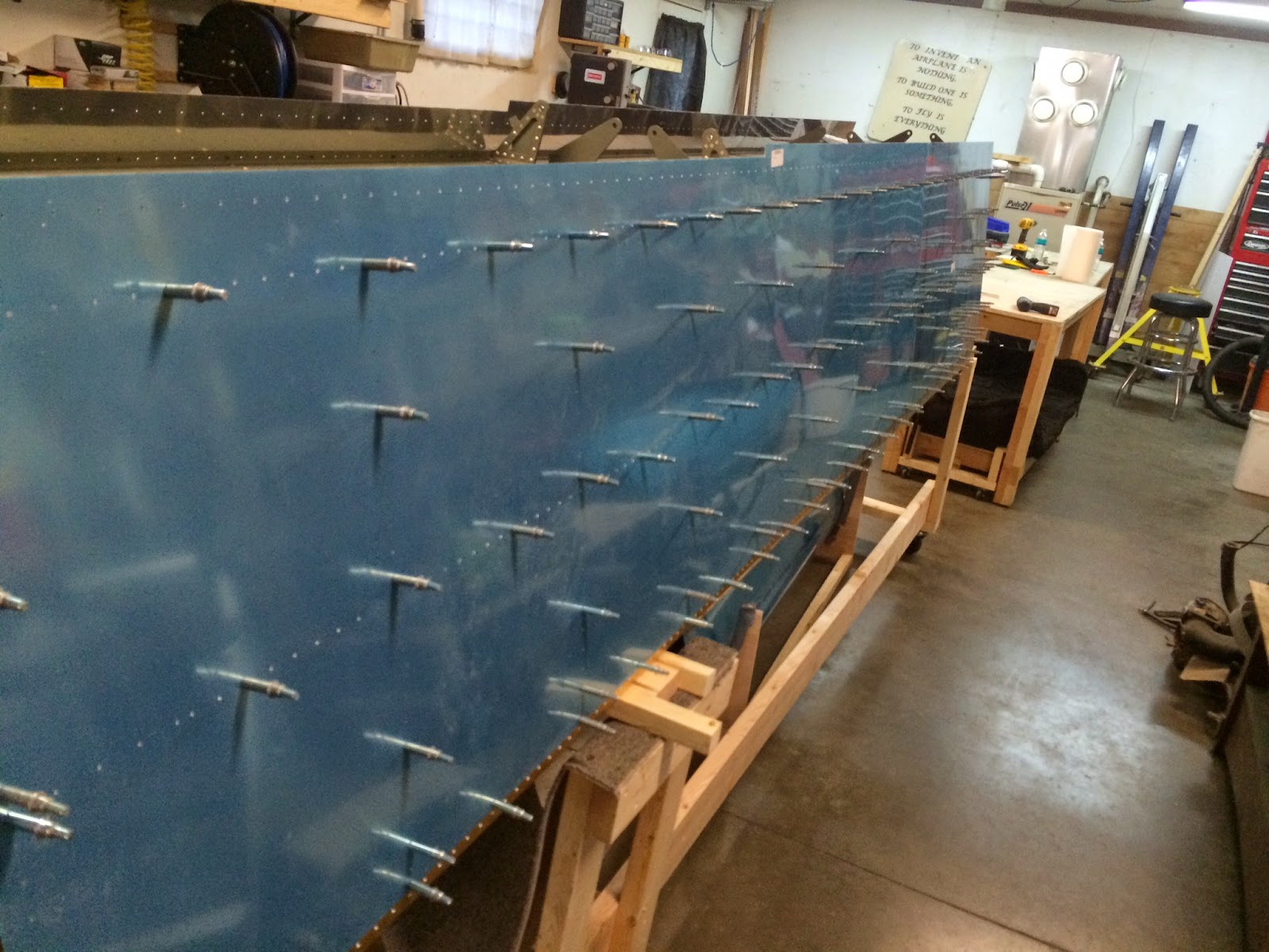
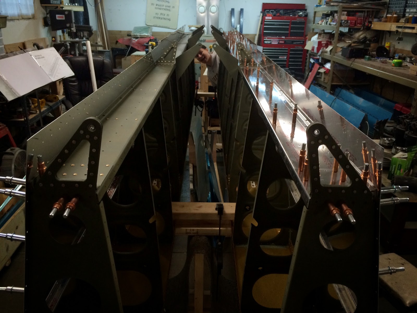
Inboard view of the wings
Outboard view of the wings
Good stopping point for today! Tomorrow we'll start the laborious and non-photogenic task of final-drilling the 500 or so holes in the skins... maybe some deburring and dimpling too, we'll see!
Subscribe to:
Posts (Atom)