Showing posts with label Cabin Cover. Show all posts

Monday, July 4, 2016

Forward Progress!!!

Well after almost 6 months of very little progress to report, I'm happy to say we had a very productive holiday weekend in the shop. Oh yeah, happy July 4!!!

Team Sarah Maggie and Mikey J back at it in the shop!

First order of business, however, was to fix our propane grill in preparation for Oshkosh later on this month... the hinge had some kind of cheap and terrible rivets holding the cover together, and it had come apart sometime last year. So, it seemed like a perfect project to fire up the rivet gun for the first time in quite a while:

A couple AN470AD4-4 and we're back in business... first rivets set in quite a while!!

Alright, now on to the fiberglass stuff. I've been wanting to get my center console and throttle quadrant up and going, so the first thing I wanted to do was put the throttle friction lock recess back into place. I did this by marking the center point of the friction lock stud, and drilling a 2.5" hole using a hole saw. Then, I took a scrap piece of 1/2" styrofoam and cut a hole out of it as well (using the hole saw with the drill in reverse):

Throttle friction lock recess

I took a second piece of styrofoam and glued it to the back of the first piece, and taped it into place behind the hole I cut in the console. After a quick layup session and some sanding, drilling, and cutting, I had this piece:
Throttle friction lock, with quadrant mounted into place

Nice!! Nothing like taking some time off from building and getting back into the swing of things with a successful first project. Next, it was time to tackle the cabin cover. We've got a couple things going on simultaneously with the cabin cover: (1) The A-pillars are nearly done after months of "5-minutes-at-a-time" work sanding and filling; (2) The B-pillars will be closed in much like the A-pillars, but that effort is just getting started. Sarah has volunteered to take charge of this task (in fact, that's what she's doing in the top photo in this post) and I fully expect them to come out better than the A-pillars that I did; and (3) The overly-complicated overhead console. While I'm happy we're taking this route, I cannot overstate the amount of extra work that "rolling your own" requires versus buying, say, the Aerosport overhead console out of the box. I think by the end of this build I'm going to be Aerosport's #1 sales rep, even though I've bought only a small handful of their products compared to what they have available :-)

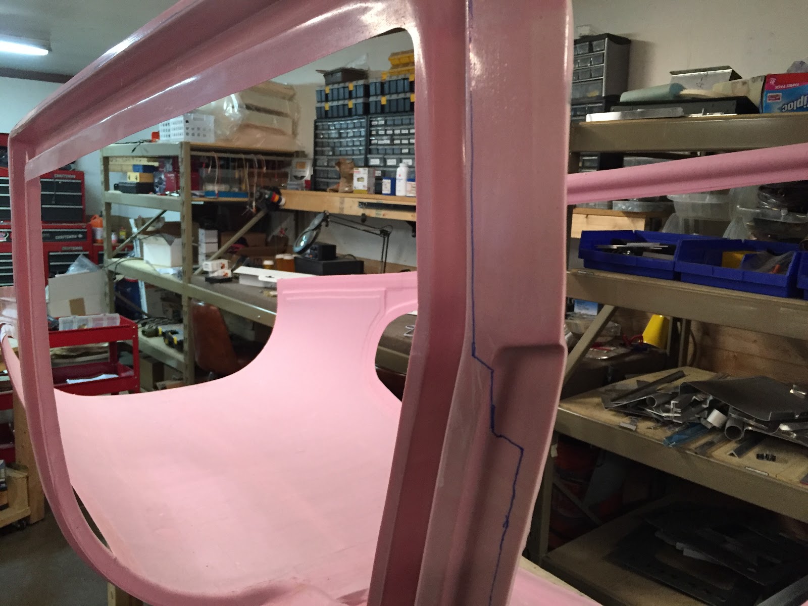
So now that the ducts are pretty close to done, it's time to build up the rest of the overhead, which will contain lights, switches, and a 4" speaker. I spent a lot of time trying to figure out what the best design would be for this, taking into consideration function, headroom, and aesthetics. I came up with this hourglass-shaped design which I'm super happy with how it turned out:

The hourglass-shaped cutout for the overhead console

The front two vent pads are visible at the bottom of the photo above. Working backwards from there, the idea is to have the vents "flow" visually into the area immediately behind, where there will be two eyeball spot lights. The center area will be raised slightly, approximately 5" wide and have an access cover containing a few switches and hiding some wiring. Moving further back, there is a mold to put a flush-mounted 4" PA speaker in the ceiling. I'm planning on using a Visaton R10S speaker with a black wire mesh grille. It *should* look pretty slick when it's done.

Moving further back from the speaker is the set of rear vent pads, which I've noticed I placed quite a bit farther forward than where they are in the Aerosport overhead console. From my mockups and measurements, these will be directly over the knees of the rear seat occupants, which is where I envisioned to be the best place for them. Maybe they are better further back? Oh well, too late to change that now. Lastly, there will be another area for two more eyeball spot lights for the rear seat occupants.

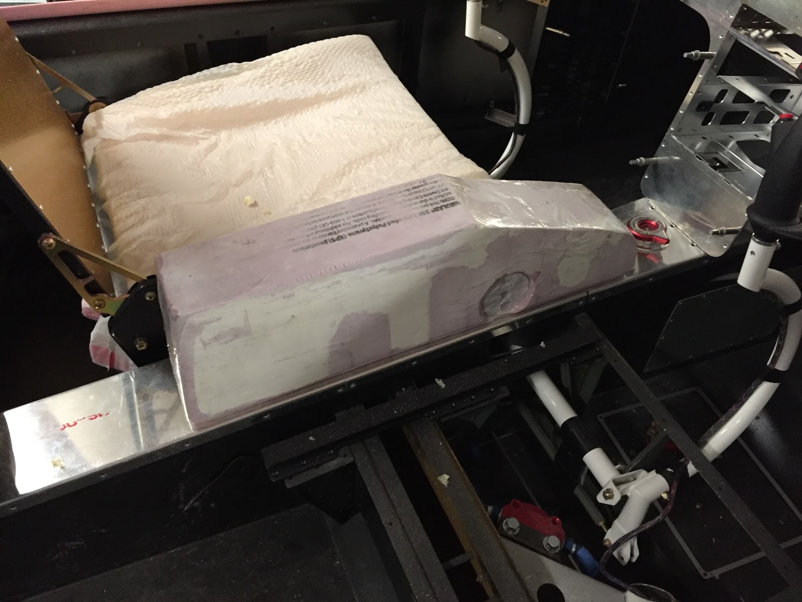
After mocking everything up with pink foam, I had an idea to try something different to fill in all the gaps and round off all the transitions: Great Stuff spray foam. We've dabbled with it plenty in the past, but this is the first time I'm using it for mold-making. I laid down a sheet of plastic film and got to work:

Using spray foam to fill in the gaps, and bucking bars to hold everything in place

Side view of the current state of affairs

Now to let the foam cure and get to sanding it all back down again!

Tuesday, February 23, 2016

Back To The Grind

Decent progress this last week, I guess. I'm finding that it's harder to gauge how far things are coming along with fiberglass work, because it's much more of a subjective art form than it is a concrete, step-by-step process. I think I'm much more of a step-by-step kinda guy.

We've continued with the A-pillars in the cabin cover, filling and sanding, filling and sanding. Complex curves are tough, but we've found out that using the right sanding block is the key to it. I made a sanding block out of a piece of 2" PVC pipe that is about 6" long, and hold it at about a 45-degree angle to the curve of the A-pillar. In this way, the roughness of the filler slowly sands away to become smooth with the natural curvature of the pillar.

The A-pillars, maybe about halfway done sanding and filling

We also final-attached the vent ducting to the cabin cover yesterday. This was kind of a benchmark step, since it had to be done before we can design and layup the overhead console itself, which will cover most of the ducting you can see now. It will also enable me to continue with the switch pod, and get everything to play nicely together. Lastly, we can also start on the B-pillar closeouts, which will be a similar process to what we're doing with the A-pillars, although hopefully not as difficult.

The vent ducting final-attached to the cabin cover. You can also see the spray foam making the general (initial) shape for the B-pillar closeouts

That's pretty much it on the fiberglassing front. In other news, I've done a bit more work in the tailcone area as well. I've attached the master and crossover solenoids to the battery mount, and re-made the yaw damper servo mount out of a slightly bigger sheet of aluminum, allowing me to mount the Garmin GDL-39R receiver next to the yaw damper servo.

Yaw damper servo (right bottom), Pitch servo (right top), GDL-39R (center), crossover solenoid (left)

Battery tray and master solenoid (left), crossover solenoid (right)

It came out pretty good so far! I'm excited to start wiring this stuff up. I did make my first RG400 BNC cable too, connecting the GDL39R to the TED transponder antenna located in the free area just aft of the elevator bellcrank. I watched a youtube video from SteinAir found at this link: https://www.youtube.com/watch?v=xPyLeBIcf9c, and it was really not a whole lot different than crimping standard household RG6 cable, other than using a slightly different crimper and the need to crimp a pin to the center conductor. The principle is pretty much the same though. I look forward to making the 10-20 more BNC cables necessary for the rest of the airplane!

Lastly, I had a question from a fellow RV-10 builder about the battery tray that I modified, so I'll describe what and why I did stray from the original Vans design F-1035 Battery mount.

The F-1035 battery mount is designed for a single Concorde RG-25XC battery, which has a footprint of 7.5" x 5". Many folks prefer to use an Odyssey PC925, which has a footprint of 7.05" x 6.64". Lastly, folks that run a dual-battery system typically install two Odyssey PC680's, each with a footprint of 7.15" x 3". Since I'm planning on having a "true dual" electrical system on this airplane, I'd like to go with the last option. However, I wanted to design a battery tray that would still have some flexibility in its design, in case someday I want to go back to a single battery setup, or maybe even move one of the two batteries up front for CG purposes.

After tossing around this idea for a bit, I decided to modify the factory mount to be 7-1/4" wide and 7-1/2" long, with provisions to attach a small 3/4-wide aluminum angle divider in the center (pictured above) and/or at the back. In this way, I can install two PC680's with a 3/4" gap in the middle and a 3/4" barrier in the back; a single PC925 with a 3/4" barrier in the back; or a RG-25XC in the original lengthwise configuration. There is an additional 3/8" nutplate installed between the two original 3/8" nutplates, so that I can attach a third hold-down bolt in that location to help keep everything secured and properly spaced.

The tray was modified by cutting off the side walls and taking some extra pieces of aluminum sheet and 1/8" angle pieces to make some extensions to "patch" into the existing part. You can see the two double rows of rivets in the photo above where the seam is. All in all, I'm very happy with how it has turned out, however I haven't yet actually installed any batteries, so the jury is still out as to whether or not it will work as I expect!

Hopefully that helps answer the question about the battery tray. Next post will likely be from back in fiberglassing hell! :-)


Thursday, February 4, 2016

Engine Update - More Fiberglass

So I've been pretty consistently lazy with updating the blog lately, sorry about that. I guess it isn't as fun spending days and days doing layups, sanding, filling, sanding, filling, doing more layups, sanding, filling, then throwing the whole thing away and starting over.... haha. But we're learning. There just isn't that much that's happened yet that makes for an interesting blog post, which I feel is somewhat in contrast to the progress we sometimes make following along in the plans and completing all the steps in order. I feel like I haven't even looked at the plans at all in at least a month now!

Before I get to the fiberglass, a quick note on the engine. I believe I've mentioned in the past that one of the parts of this build that I was excited about the most was overhauling/building the engine myself. Being a "car guy" and having overhauled many car engines in the past, I was very excited about the prospect of doing the same on the RV-10. However, as time has gone on and we've made it this far, a thought started to occur to me that maybe it would be a better idea to let the pros handle this. I mean after all, with all the time, money, blood, sweat and yes tears put into this project so far, why put the whole project in jeopardy by attempting to do the engine myself? Although these Lycoming engines are quite simple in design, anyone familiar with them will tell you there are a surprising number of gotchas and tricks-of-the-trade that only the professionals who do this every day really know how to handle.

And even the pros have trouble sometimes! I became familiar with a situation not too long ago involving a locally-owned airplane having some engine trouble at an airport a few hundred miles away. Luckily the pilot fought the urge to "get home and check it out" and decided to stay on the ground, quickly realizing that the engine actually had a major issue, requiring a complete and immediate overhaul. The engine was a mid-time Lycoming that had been previously overhauled by a top-notch and very experienced mechanic. I personally saw the look of disappointment and confusion on his face when he heard the news. It's very likely that the problem had nothing to do directly with the quality of work that he performed, but even so, his look and attitude towards that situation certainly left an impression.

I tell that story because that was sort of the beginning of the end for me with respect to building the engine myself. The more I thought about it, the more I became certain that this was a task best handed off to someone more experienced and capable. So, I called around to a few places and have made plans to bring my setup to Poplar Grove Airmotive in Poplar Grove, IL. They are a well-respected engine overhaul shop and come highly recommended by several pilot friends who have used their engine overhaul services. They quoted me what seems to be a fair price for engine assembly and dyno testing, and hopefully what I get back from them will be a zero-time, fully airworthy and reliable engine ready to perform for us.

So in preparation for sending the engine into their shop, I've placed a few orders for the parts I still need to make this engine complete. These include bearings, gaskets, hoses, nuts and bolts, as well as some additional components. Some of the bigger-ticket items include the starter and two B&C alternators (BC460-H and BC462-3H), as well as overhauling the fuel servo, fuel pump and flow divider by Airflow Performance. Hopefully, I'll have a complete stack of parts ready to go by the end of the month, and I can haul it all over to IL to get that process started!

In the meantime, we're continuing with our work on fiberglass. I started making the center console/quadrant/armrest, and tried to take a few pictures along the way:

NOTE: It will be painfully obvious that the design of this console is "inspired" by the new Aerosport "Quad Console" armrest... it can probably best be described as a poor-man's homemade version of it. Hopefully it will be just as functional and just nearly as pretty when complete!

Spent many DAYS making a foam "plug" that will be used to make the center console.

Random photo of the adhesive being used to bond the foam: Glidden Gripper primer! I found this trick from watching a youtube video where several different adhesives were used for comparison. Many traditional adhesives will actually melt the foam and can't be used, leaving few alternatives that actually make a good bond... this stuff works great, and cleanup is painless!


Approximate location on the tunnel. The throttle quadrant will be in the slanted forward part, and there will be a padded armrest cover that opens into a storage box (big enough to hold a sectional chart!) inside the main area.


After layups and initial trim: The console is made in two separate halves, one slightly overlapping the other, so that they can be removed from the plug and then bonded together as a hollow piece.

The first few clecos being installed to clamp it together for bonding

Since these photos were taken, the console has been bonded together, sanded, filled, and then cutouts have been made in the top, front and back for various panels and openings. It's coming together, but man this isn't something that can just be built in a day.

Other parts coming along are the "A-pillars" in the cabin cover, which I've successfully run conduit through and sealed in place with spray foam. I shaped the foam to approximate what I wanted and then put a single layup over it. This has resulted in an EXTREMELY wavy base layer, on top of which I will need to fill and sand everything to become smooth and properly contoured. I'll try and post some photos of that endeavor next time.

We have some plans coming up over the next week or two, so I wouldn't count on much work getting done on the plane until maybe after Valentine's day or so... but I will keep trying to find some time to post updates!


Monday, January 11, 2016

Overhead Console - Panel

Quick update today... got some decent work in over the weekend but really doesn't feel like much has changed. I guess a lot has been accomplished, but nothing can really be checked off yet, and it feels like everything is in a half-completed state (I'm finding this seems to happen periodically). Also, I'm really finding out what a specialized skill fiberglassing is. People who are good at it make it look so darn easy, and there are plenty of beautiful examples that can be found online of parts people made for their airplanes from fiberglass... I wouldn't say mine fall into that category yet. The good news, though, is I feel like I'm learning a lot, and eventually I'll be able to make the parts I need for this project.

I was able to re-make the ducting system for the overhead console, using a slightly modified design and an improved method of actually laying the glass. It came out much better this time, but it certainly still has its flaws. The good news is, of course, these parts aren't structural in any way, so as long as they don't fall off the ceiling in flight or something, I think we're ok from a safety standpoint.

Version 2.0 of the overhead ducting system

It's pretty similar in theory to the first one-- the duct on the left side brings air to the front two vents, and the duct on the right side brings air to the rear two vents. There will be a pair of servos in the tailcone controlling flow to each of these two ducts, and in this way we can control the amount of fresh air going to the front and back.

Now, the idea is to cover these ducts with the actual console itself. Since these ducts will be mostly hidden beneath the console, I'm not too terribly worried about how perfect they look, as long as they are airtight and have a good bond to the cabin cover. If all works out like what's in my mind, the final product will be a seamless-looking console that has four vents, four spotlights, some access panels, and some recessed accent lights to serve as dome and cargo lighting. Oh yeah, and the switch pod. Still at square one for that... also need to build a center console for the armrest and throttle quadrant. Sheesh! Lots more fiberglass to do.

In between epoxy curing sessions, I also started work on the panel. I had previously purchased a 24" x 48" sheet of 0.070" aluminum from Aircraft Spruce and intended to cut out my own (slightly larger) version of the instrument panel Van's gives you. I began by tracing out the original instrument panel and marking all the attach holes that go along the upper edge. Then, I drew a straight line across the bottom that is about a half inch below where the standard switch bar ends, thus making the panel about a half inch taller than stock, and all in one sheet. Lastly, I drew in lines for the center console and side vents and began cutting everything out. I used a combination of a jigsaw, dremel, belt sander, and an array of files:

New instrument panel after initial cut

Looks good! I sat down in the left seat and discovered there was still plenty of room for my knees too. The extra half inch of height really isn't noticeable at all from a comfort side of things, but it totally gives the appearance of having WAY more panel space...cool!

So now comes the fun part: laying out where all the instruments are going to go. I've agonized over this for months now... so many options, each with their advantage and disadvantage. It's time to make my mind up and just go for it. If I end up hating the layout, I guess I can always try again. Hopefully that won't happen.

The basic idea for the panel layout is to have the 10" G3X touch screens centered for each pilot/copilot, and the Mini-X backup EFIS in the center. The GTN750 and GMA350c audio panel will be mounted into the console (a bit low compared to many other configurations, more on this later), and the GMC307 flight control panel will be mounted high and center. This layout seemed to work the best so that the aircraft can be piloted just as easily form the left seat as the right seat-- one of our main requirements. So, I did some more measuring, tracing, and cutting, and ended up with this for a panel:

Instrument panel after cutouts for avionics

Good stuff! I found it wasn't nearly as hard to cut it out as I was thinking it might be. The hardest part was drawing all the lines to be perfectly straight and square. If you look super close there are a few cut lines that aren't perfect, but the mounting of all the instruments covers it all up nicely. So far so good... now it's on to switches!

I'm struggling a bit with the layout of the switches, but I think I have a general idea of where things are going to go. I'll post a diagram at some point when I finalize the layout, but right now I'm at the point of figuring out exactly what model I need for every single switch, indicator, and potentiometer. Kind of a fun task, but very tedious too. Also, turns out quality switches aren't the cheapest thing in the world. I'll be placing a pretty hefty order with Digikey in the coming days that should cover most of our immediate needs for switches and the like, then we will go from there.

That's it for now! Next up, more work on the overhead and panel...


Friday, December 4, 2015

More Cabin Cover - Avionics Order

Today we finished all (or at least most) of the prep work on the cabin cover according to the plans! Unfortunately, there is a LOT more prep work to do on this piece that is not mentioned in the plans. We need to build an overhead console, figure out the lighting and ventilation systems, and finish off the fiberglass in all the areas that will be exposed. This will be some fun work, but it will likely take several months before it's all complete. We'll just have to make sure we keep at it!

Anyway, the first thing we did was match-drill the aluminum strip set aside from back in section 10 (tailcone). I had to think for a second where I put the darn thing, and eventually found it.

The aluminum strip set aside in 10-12 Step 1. I wrote "SAVE!!" on it in a number of places.

Match-drilling this, along with the two side strips was fairly straightforward, maybe just a bit boring and tedious, but we got through it pretty quickly. Next, we had to countersink all the holes in the cabin cover that we had made. I whipped up a small 0.032" spacer as recommended in the plans to hold the microstop square with the flange on the cover.

Countersinking the cabin cover, using a 0.032"spacer

I dimpled the other side of the spacer with a #30 dimple to trial-fit the countersinks

Otherwise, that's basically it! The next part of the plans basically has you final-install the cover to the fuselage. We're not quite ready for that yet, now we still have to design and fabricate an overhead console and all kinds of other stuff. Hopefully we'll get started on some of that this weekend.

In other news, we placed our order for avionics today.... OUCH. Biggest single purchase I've ever made, short of buying a house. I've been talking with Jed at Stein Air for a couple weeks now, narrowing down my options and figuring out what exactly we're going to do. Here's the short list of components we got:
  • Garmin G3X Touch 10" Dual Display w/ EIS & XM
  • Garmin GNS 750 Touchscreen NAV/COM navigator
  • Garmin 3-axis autopilot with GSA-28 servos and GMC-307 control panel
  • Garmin GTR 20 COM radio (for COM2)
  • Garmin GAD 29 ARINC interface
  • Garmin GAD 27 integrated controller (brand new product just announced last month)
  • Garmin GMA 350c audio panel w/ Bluetooth
  • Garmin GTX 23ES transponder with ADSB-out, paired with GDL39R ADSB-in
  • Grand Rapids Mini-X backup EFIS system
  • All the connectors, wiring, sensors, antennas, and more needed to get all this wired together
By the time I added everything up, I wanted to cry. Hopefully, I won't regret this purchase decision, or Garmin won't announce their new line of avionics in January or something that are twice as good and cost half as much. This really was the time to buy though, for a few reasons: (1) Garmin has their "stack up the savings" holiday rebate program going on right now through the 15th, that will give me $1000 back in rebates; (2) my credit card is giving me a 2% cash back deal through the holiday season, which for this kind of purchase is a good chunk of change; and (3) Stein Air gave me a heck of a package discount price... I couldn't come within $500 anywhere else.

As nervous as I am about the purchase, I'm pretty confident that this is the right system for me though, after lots of careful consideration and research. Excited to get started wiring all this stuff up! Quick plug for Stein Air, they have been awesome to work with so far and I'm very happy with the experience up to this point. With a reputation like theirs, I'm quite sure the rest of the experience will go just as well!


Thursday, December 3, 2015

More Cabin Cover

So today we continued with the cabin cover, this time drilling the four holes in the top of the cover to hold the WD-1043 Center Cabin Brace. This series of steps presented a few unique challenges, the first of which was to figure out how in the world do you precisely determine the centerline of the cabin top? The fiberglass is very rough and uneven, and there is no obvious way to determine where the middle is. We finally figured out that the middle can be found on the exterior side of the top, and you can then extend that center line forward and around to the inside.

Once you've marked the center line, you have to match-drill the brace into the fiberglass all the way through to the exterior. The plans are kind of scary here, warning you to ensure you drill perpendicular to the parts. Since the cabin cover is so thick in this area, even a small variation can make the four holes look like they were marked off on the exterior by a drunk person. No one wants that! I ended up doing pretty good I think... not perfect, but pretty good.

Once the four holes were drilled, we removed the cover from the fuselage and began cleaning out all the dust and chips. I fabricated four small tubes as called out in the plans to insert into these four holes we just made in the top. The idea is that these tubes reinforce the attachment point and allow the screws to grip a little better. They also look pretty cool after countersinking them into place:

The four F-10106 spacers before countersinking - don't spend an hour like I did making four spacers EXACTLY to the correct length per the plans... you're just going to whittle them down anyway when countersinking. Just make the interior end nice and leave the exterior end rough.

After countersinking-- looks pretty neat!

Word of advice to future builders: be careful when countersinking these! While running the drill with the countersink, it can grab the spacer and begin spinning the whole thing inside the cabin cover. If your finger is on the other side holding the spacer flush, the spacer basically acts like a mini hole saw and you'll end up with a small, perfectly circular piece of skin that used to be part of your fingertip. Ask me how I know :-)

Next on the agenda is match-drilling the backing strips, but we'll save that for another day... stay tuned!


Wednesday, December 2, 2015

Cabin Cover

Well it's been an interesting week so far! Been putting together our avionics order, and started fabricating a mount for the circuit breaker panel to go on the lower left side of the forward fuselage, under the air vent. We've also gotten a few short sessions of sanding the cabin top in here and there, but it kinda dragged on over a number of days with no real feeling of forward progress. Finally though, the cabin top was sanded enough to fit properly in place, and allow the aft top skin to be clecoed in place over it. This is easily one of the top 10 most exciting moments so far in the build, because all of a sudden it strikes you-- hey, you've got a roof!

The next thing to do is match-drill a number of holes along the mating parts and begin to cleco the cabin top to the rest of the structure.

Drilling the forward-most row of holes in the aft top skin into the aft flange of the cabin top

Drilling the row of holes along the top of the mid fuse side skins

Clamping the door frames into place to get everything aligned properly for drilling

That's pretty much it for today... lots of sanding and drilling. Stay tuned for more sanding and drilling!

Thursday, November 26, 2015

Cabin Cover

Happy Thanksgiving! In between sleeping in this morning and getting ready to go do the family thing this afternoon by making my spinach and artichoke dip, we found some time to wander into the garage and continue on the cabin cover.

Lots of sanding and mess-making! Wow the sides along the door sills need to be trimmed down to almost nothing. Like many builders before us, we are unimpressed with fiberglass work. It's dirty, it smells funny, and you have to wear breathing masks and eye protection and all that stuff. In the end though, we were able to sand away enough material to get the cabin cover to slide all the way down and into place... ok, it was worth it!

Cabin Cover fits in place for the first time!

Still LOTS more sanding and fine-tuning to do, but this is pretty close at least for the initial fit. Definitely worth stepping back and admiring our work!

Ok, now on to more important things for the day... gotta go make that dip and go eat some turkey. More building to come this weekend!

Thursday, November 19, 2015

Cabin Cover - First Cut

We accomplished the first cut of the cabin cover tonight... woohoo! It went mostly "okay"... definitely a big gear shift from all the aluminum metal work that we've grown accustomed to. Sarah will be involved quite a bit more these days too, since she has earned the esteemed title of "fiberglassing expert" on this team (you may remember from one of our first-ever posts about the EAA SportAir Workshop we attended, I took the sheet metal course and Sarah took the fiberglass course). In truth, we both have a lot to learn about fiberglass work, and we'll be taking it slowly and carefully, and hopefully not end up splitting the cover in half or something and end up needing to order a new one. I'm fairly certain this thing isn't cheap.

So with that, it was time to get started! We donned our dust masks and safety glasses, got the shop vac ("R2") handy, and grabbed our secret weapon: a Dremel MultiMax oscillating saw. Sarah mentioned that they used one of these in her fiberglassing class to cut cured pieces, and it cut through them like butter and made very little dust. Excited to see how it works!

Team Mike & Sarah ready to cut some 'glass!

Moments after this photo was taken, we discovered that the oscillating saw works TERRIBLY on the cabin cover. It bounces all over the place and barely made any kind of cut at all. On the bright side I guess it didn't make much dust either, so it did live up to that end of the bargain. So, we went back to the normal plan and grabbed the air cut-off tool. After installing a fresh cutting disk, we got started. In a demonsration of her multi-tasking abilities, Sarah took this video of the first cut while holding the vacuum nozzle:

First cut of the cabin cover!

It's a relatively slow process, and even though we have a decent-sized air compressor, I've long known that it isn't quite big enough to run the air-hungry cutoff tool continuously. It will go for a minute or two but then runs out of steam and needs a few minutes to recharge. No big deal, just something to be aware of. After a handful of cut/recharge cycles, we had made all the necessary cuts to attempt an initial fit of the cover!

Initial fit of the cabin cover - doesn't quite slide into place yet!

Nowhere near enough yet! That's ok... hey, at least we didn't cut off too much. Now it's going to be many cycles of cutting and sanding, trial fitting, and figuring out where the high spots are that need more cutting and sanding. This was enough for one night... but we'll get back to this soon!


Wednesday, November 18, 2015

Cabin Top Prep

Not a whole ton of work on the plane today, but what wasn't accomplished physically was certainly made up for by overcoming the mental hurdle of transitioning to fiberglass work... today marks the first day of Section 43 - Cabin Cover!

Although no actual "fiberglass" work started yet, we did rearrange the shop a bit and perform the first few steps in the section, including marking 7 spots on each of the mid cabin decks, and marking off all the scribe lines on the cabin cover itself. I now see what people are talking about when they say the scribe lines aren't really all that great-- they're definitely not very straight and I think they only give the general idea of what needs to be cut!

Marks on the mid cabin decks for eventually match-drilling the cabin cover screw holes

Traced the scribe lines with a blue Sharpie to denote the first cut lines


An interesting step cut that will have to be made

Not all the scribe lines were very straight!

So that's pretty much it for today, but tomorrow we should be able to actually start cutting and sanding this thing.... eeek!!!!