Showing posts with label Avionics. Show all posts

Tuesday, February 23, 2016

Back To The Grind

Decent progress this last week, I guess. I'm finding that it's harder to gauge how far things are coming along with fiberglass work, because it's much more of a subjective art form than it is a concrete, step-by-step process. I think I'm much more of a step-by-step kinda guy.

We've continued with the A-pillars in the cabin cover, filling and sanding, filling and sanding. Complex curves are tough, but we've found out that using the right sanding block is the key to it. I made a sanding block out of a piece of 2" PVC pipe that is about 6" long, and hold it at about a 45-degree angle to the curve of the A-pillar. In this way, the roughness of the filler slowly sands away to become smooth with the natural curvature of the pillar.

The A-pillars, maybe about halfway done sanding and filling

We also final-attached the vent ducting to the cabin cover yesterday. This was kind of a benchmark step, since it had to be done before we can design and layup the overhead console itself, which will cover most of the ducting you can see now. It will also enable me to continue with the switch pod, and get everything to play nicely together. Lastly, we can also start on the B-pillar closeouts, which will be a similar process to what we're doing with the A-pillars, although hopefully not as difficult.

The vent ducting final-attached to the cabin cover. You can also see the spray foam making the general (initial) shape for the B-pillar closeouts

That's pretty much it on the fiberglassing front. In other news, I've done a bit more work in the tailcone area as well. I've attached the master and crossover solenoids to the battery mount, and re-made the yaw damper servo mount out of a slightly bigger sheet of aluminum, allowing me to mount the Garmin GDL-39R receiver next to the yaw damper servo.

Yaw damper servo (right bottom), Pitch servo (right top), GDL-39R (center), crossover solenoid (left)

Battery tray and master solenoid (left), crossover solenoid (right)

It came out pretty good so far! I'm excited to start wiring this stuff up. I did make my first RG400 BNC cable too, connecting the GDL39R to the TED transponder antenna located in the free area just aft of the elevator bellcrank. I watched a youtube video from SteinAir found at this link: https://www.youtube.com/watch?v=xPyLeBIcf9c, and it was really not a whole lot different than crimping standard household RG6 cable, other than using a slightly different crimper and the need to crimp a pin to the center conductor. The principle is pretty much the same though. I look forward to making the 10-20 more BNC cables necessary for the rest of the airplane!

Lastly, I had a question from a fellow RV-10 builder about the battery tray that I modified, so I'll describe what and why I did stray from the original Vans design F-1035 Battery mount.

The F-1035 battery mount is designed for a single Concorde RG-25XC battery, which has a footprint of 7.5" x 5". Many folks prefer to use an Odyssey PC925, which has a footprint of 7.05" x 6.64". Lastly, folks that run a dual-battery system typically install two Odyssey PC680's, each with a footprint of 7.15" x 3". Since I'm planning on having a "true dual" electrical system on this airplane, I'd like to go with the last option. However, I wanted to design a battery tray that would still have some flexibility in its design, in case someday I want to go back to a single battery setup, or maybe even move one of the two batteries up front for CG purposes.

After tossing around this idea for a bit, I decided to modify the factory mount to be 7-1/4" wide and 7-1/2" long, with provisions to attach a small 3/4-wide aluminum angle divider in the center (pictured above) and/or at the back. In this way, I can install two PC680's with a 3/4" gap in the middle and a 3/4" barrier in the back; a single PC925 with a 3/4" barrier in the back; or a RG-25XC in the original lengthwise configuration. There is an additional 3/8" nutplate installed between the two original 3/8" nutplates, so that I can attach a third hold-down bolt in that location to help keep everything secured and properly spaced.

The tray was modified by cutting off the side walls and taking some extra pieces of aluminum sheet and 1/8" angle pieces to make some extensions to "patch" into the existing part. You can see the two double rows of rivets in the photo above where the seam is. All in all, I'm very happy with how it has turned out, however I haven't yet actually installed any batteries, so the jury is still out as to whether or not it will work as I expect!

Hopefully that helps answer the question about the battery tray. Next post will likely be from back in fiberglassing hell! :-)


Tuesday, January 19, 2016

Odds & Ends

So it's been a while since the last update. Things are going well, but slowly. We've been working on sanding the inside of the cabin cover, installing conduit along the front "A-pillars" and "B-pillars", and filling in the voids with spray foam to then cover with fiberglass. I'm also trying to come up with the desired shape for the overhead switch panel, which will contain all my lights and dimming controls. I received my switch and terminal order from Digikey the other day, so I took a piece of scrap aluminum and quickly made a (very) rough mockup of what I had envisioned for the switch panel:

Overhead switch panel, v0.0.1

It came out "okay"... I think there needs to be a bit more room vertically between the dimmers and the switches, and also maybe just a smidge more space between each toggle, although I can live with it as-is. The idea will also be to have both the upper and lower edges of the panel curved, to better fit in the given space and give it kind of a more elegant look. At least that's what I'm going for-- it may very well end up looking like some kind of super-cheesy clown smile instead. We'll see.

I need to figure out how to illuminate these too. Right now the thought is to make a piece of clear acrylic that is painted a solid opaque color, and is then etched to allow light to pass through for all the legends and graphics. Another option would be to get a panel made from a place like engravers.net and backlight them with LED's. Although I like that idea (and I've seen some really sweet-looking panels made this way), I'd like to first try the acrylic method and see how far I can get. This will be on a growing list of back-burner projects that I'll get to, eventually.

Continuing on the electrical side of things, I also received my order for 12V accessory plugs. I kind of "splurged" on this and went with the VW/Audi parts that I've seen discussed on the forums. They're pretty slick-looking-- they have a spring-loaded door with "12V" marked on the front, and should provide a nice finishing touch to the interior when it all comes together. I'd take a picture, but one of the parts I received was incorrect and I'll need to exchange that out before I can move forward on this. There will be a total of three outlets in the plane: one for each of the two front passengers, and a third in the middle for the back seat.

I'm also working on preparations for the avionics. Specifically, I'm drafting all of my own wiring diagrams for the plane using the program Kicad, an open-source schematic capture and PCB layout program I've used for quite some time on a number of different projects. This is of course BY FAR the biggest of those projects, and it's going to take many weeks (if not months) to finalize a wiring diagram before I can actually cut, strip and crimp my first wire. The diagram will be comprehensive in nature and cover all of the avionics interconnects (of which there are many hundreds) as well as ship's wiring for things like lights, trim, flaps, etc etc. It's a fun task (yes, I actually enjoy this stuff) but it's also very tedious and does take a long time. It also has a tendency to make me cross-eyed after a few hours of reading through the thousands of PDF pages of install manuals and datasheets, trying to figure everything out. I'm getting there, slowly but surely!

Alright, I've talked enough. Here's a few pictures of many of the other accomplishments made this last week:

Rigged up the GSA28 pitch servo, and installed the optional Van's RV-10 ADAHRS tray to hold another GSA28 servo for the yaw damper. Fabricated a bracket to hold the yaw damper bellcrank, centered behind the elevator bellcrank. I'll probably re-make the ADAHRS tray itself out of thicker material and extend it forward slightly so I can also mount my GDL39R ADSB box. I also re-made the yaw damper arm into a more "boomerang" shape that has slightly different geometry that will work better with the movement of the rudder cables. I'll make a full post about the yaw damper and all the parts used to construct it once it's finalized.

Installed the Tosten stick grips... yay! I may cut another bit off the sticks to bring them down just a tad more. I started with them in a little high because... well... you can always cut more off but it's real hard to make them taller again!


Lastly, a quick montage of cutting out the rear NACA vent holes. Thanks to my friend Derek for stopping over and taking some of the action shots :-)
Traced the front NACA hole onto a piece of Lean Pockets cardboard, cut it out, and then traced it on this location in the aft fuselage skin. The vertical line shown is 10" back from (and parallel to) the seam between the mid fuse side skin and the tailcone, with a centerline drawn between the two rivet lines.


Me getting started with the cut using a Dremel tool

Cut almost done...

After a bit of filing, it looks great! Just the same as the holes in the front... woo!

That's it for now... until next time!


Monday, January 11, 2016

Overhead Console - Panel

Quick update today... got some decent work in over the weekend but really doesn't feel like much has changed. I guess a lot has been accomplished, but nothing can really be checked off yet, and it feels like everything is in a half-completed state (I'm finding this seems to happen periodically). Also, I'm really finding out what a specialized skill fiberglassing is. People who are good at it make it look so darn easy, and there are plenty of beautiful examples that can be found online of parts people made for their airplanes from fiberglass... I wouldn't say mine fall into that category yet. The good news, though, is I feel like I'm learning a lot, and eventually I'll be able to make the parts I need for this project.

I was able to re-make the ducting system for the overhead console, using a slightly modified design and an improved method of actually laying the glass. It came out much better this time, but it certainly still has its flaws. The good news is, of course, these parts aren't structural in any way, so as long as they don't fall off the ceiling in flight or something, I think we're ok from a safety standpoint.

Version 2.0 of the overhead ducting system

It's pretty similar in theory to the first one-- the duct on the left side brings air to the front two vents, and the duct on the right side brings air to the rear two vents. There will be a pair of servos in the tailcone controlling flow to each of these two ducts, and in this way we can control the amount of fresh air going to the front and back.

Now, the idea is to cover these ducts with the actual console itself. Since these ducts will be mostly hidden beneath the console, I'm not too terribly worried about how perfect they look, as long as they are airtight and have a good bond to the cabin cover. If all works out like what's in my mind, the final product will be a seamless-looking console that has four vents, four spotlights, some access panels, and some recessed accent lights to serve as dome and cargo lighting. Oh yeah, and the switch pod. Still at square one for that... also need to build a center console for the armrest and throttle quadrant. Sheesh! Lots more fiberglass to do.

In between epoxy curing sessions, I also started work on the panel. I had previously purchased a 24" x 48" sheet of 0.070" aluminum from Aircraft Spruce and intended to cut out my own (slightly larger) version of the instrument panel Van's gives you. I began by tracing out the original instrument panel and marking all the attach holes that go along the upper edge. Then, I drew a straight line across the bottom that is about a half inch below where the standard switch bar ends, thus making the panel about a half inch taller than stock, and all in one sheet. Lastly, I drew in lines for the center console and side vents and began cutting everything out. I used a combination of a jigsaw, dremel, belt sander, and an array of files:

New instrument panel after initial cut

Looks good! I sat down in the left seat and discovered there was still plenty of room for my knees too. The extra half inch of height really isn't noticeable at all from a comfort side of things, but it totally gives the appearance of having WAY more panel space...cool!

So now comes the fun part: laying out where all the instruments are going to go. I've agonized over this for months now... so many options, each with their advantage and disadvantage. It's time to make my mind up and just go for it. If I end up hating the layout, I guess I can always try again. Hopefully that won't happen.

The basic idea for the panel layout is to have the 10" G3X touch screens centered for each pilot/copilot, and the Mini-X backup EFIS in the center. The GTN750 and GMA350c audio panel will be mounted into the console (a bit low compared to many other configurations, more on this later), and the GMC307 flight control panel will be mounted high and center. This layout seemed to work the best so that the aircraft can be piloted just as easily form the left seat as the right seat-- one of our main requirements. So, I did some more measuring, tracing, and cutting, and ended up with this for a panel:

Instrument panel after cutouts for avionics

Good stuff! I found it wasn't nearly as hard to cut it out as I was thinking it might be. The hardest part was drawing all the lines to be perfectly straight and square. If you look super close there are a few cut lines that aren't perfect, but the mounting of all the instruments covers it all up nicely. So far so good... now it's on to switches!

I'm struggling a bit with the layout of the switches, but I think I have a general idea of where things are going to go. I'll post a diagram at some point when I finalize the layout, but right now I'm at the point of figuring out exactly what model I need for every single switch, indicator, and potentiometer. Kind of a fun task, but very tedious too. Also, turns out quality switches aren't the cheapest thing in the world. I'll be placing a pretty hefty order with Digikey in the coming days that should cover most of our immediate needs for switches and the like, then we will go from there.

That's it for now! Next up, more work on the overhead and panel...


Tuesday, January 5, 2016

Air Trip!!!

Well, I've been waiting for some decent weather to fly up to Farmington, MN (on the outskirts of Minneapolis) to pay a visit to Stein Air to pick up my avionics order in person. Of course, visiting in person wasn't explicitly required for any reason, but it actually worked out to be the same--or even slightly lesser--cost to fly up there myself instead of having all the stuff shipped to me. Plus, it was a great excuse to fly, and I wanted to meet and shake hands with the folks I'd been dealing with!

The only problem we had was that it seemed as though the weather was continually conspiring against us for the last 2-3 weeks in a row, keeping us from making it up there. Although I do have an instrument rating, the Archer we currently fly isn't really cut out for it. Plus, most days the weather wasn't even good enough to fly IFR in a small plane... freezing fog, ice, snow, gusty winds... all the stuff we pilots have nightmares about. Better to be on the ground wishing we were up in the sky rather than the other way around, right?

Anyway, today we FINALLY got some good weather to make the relatively short ~1hr trip up there. Unfortunately Sarah was stuck at work, but I was able to enlist my friend Derek to tag along and keep me company on the journey. So, we hopped in "Julie" the Archer and blasted off to the north!

Negotiating through the outermost rings of the Minneapolis Class B airspace and landing at Airlake Airport (KLVN) proved to be very straightforward and made for an easy flight. Upon landing, I gave Stein a call and Jed picked us up in Stein's really nice BMW SUV... I'm not used to fancy vehicles like that! We had a great visit, but like a doofus I forgot to take any pics while we were there. We got the "nickel tour" and met most of the employees, who were all hard at work wiring up avionics, making harnesses, cutting panels on the CNC mill, and drafting schematic diagrams on a giant computer monitor. Jed even showed us their new laser etching machine that they apparently just started using within the last month or two. Neat! It was definitely a clean, well-organized facility, and everyone was clearly hard at work doing "real stuff" putting something together for an assuredly happy customer somewhere around the world. They were all happy to take a minute out of their day though to say hello and show us what they were up to. It was really cool... I felt fortunate that we live close enough to have been able to make the trip up feasible... if you ever have the opportunity to visit, I definitely recommend it!

!!!Thanks again to Jed, Stein, and all the other employees at Stein Air for a great visit!!!

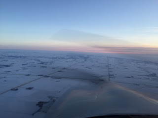
With that, and a short ride in the Beemer back to the airport, we carefully packed up our mother load of boxes into the Archer and blasted off to the south. As the sun started to set, I had to snap a couple photos:

Southbound from the Minneapolis area

Crossing from Minnesota into Iowa - pretty rural, but still a very serene beauty.

Passing over New Hampton, IA... this town looked almost "fake" from the air because it was so pretty with the sunset!

Touching down at KIIB, we drove back to Marion, dropped Derek off and finally got home. Sarah was eagerly awaiting my return with "the goods," and after a quick unloading and sorting session we had an intimidating pile of avionics to go through!

N165MJ avionics (with a few goodies from Stein) after unloading and sorting... love the red "We're not happy 'til you're broke" keychains in the middle! A dose of reality... ouch.

Had to unbox the GTN-750 and one of the G3X Touch displays to have a look... it's like Christmas :-)

Anyway, with all that it's time to finish up some things at work and then call it a night... coming soon, more work on the overhead console!


Friday, December 4, 2015

More Cabin Cover - Avionics Order

Today we finished all (or at least most) of the prep work on the cabin cover according to the plans! Unfortunately, there is a LOT more prep work to do on this piece that is not mentioned in the plans. We need to build an overhead console, figure out the lighting and ventilation systems, and finish off the fiberglass in all the areas that will be exposed. This will be some fun work, but it will likely take several months before it's all complete. We'll just have to make sure we keep at it!

Anyway, the first thing we did was match-drill the aluminum strip set aside from back in section 10 (tailcone). I had to think for a second where I put the darn thing, and eventually found it.

The aluminum strip set aside in 10-12 Step 1. I wrote "SAVE!!" on it in a number of places.

Match-drilling this, along with the two side strips was fairly straightforward, maybe just a bit boring and tedious, but we got through it pretty quickly. Next, we had to countersink all the holes in the cabin cover that we had made. I whipped up a small 0.032" spacer as recommended in the plans to hold the microstop square with the flange on the cover.

Countersinking the cabin cover, using a 0.032"spacer

I dimpled the other side of the spacer with a #30 dimple to trial-fit the countersinks

Otherwise, that's basically it! The next part of the plans basically has you final-install the cover to the fuselage. We're not quite ready for that yet, now we still have to design and fabricate an overhead console and all kinds of other stuff. Hopefully we'll get started on some of that this weekend.

In other news, we placed our order for avionics today.... OUCH. Biggest single purchase I've ever made, short of buying a house. I've been talking with Jed at Stein Air for a couple weeks now, narrowing down my options and figuring out what exactly we're going to do. Here's the short list of components we got:
  • Garmin G3X Touch 10" Dual Display w/ EIS & XM
  • Garmin GNS 750 Touchscreen NAV/COM navigator
  • Garmin 3-axis autopilot with GSA-28 servos and GMC-307 control panel
  • Garmin GTR 20 COM radio (for COM2)
  • Garmin GAD 29 ARINC interface
  • Garmin GAD 27 integrated controller (brand new product just announced last month)
  • Garmin GMA 350c audio panel w/ Bluetooth
  • Garmin GTX 23ES transponder with ADSB-out, paired with GDL39R ADSB-in
  • Grand Rapids Mini-X backup EFIS system
  • All the connectors, wiring, sensors, antennas, and more needed to get all this wired together
By the time I added everything up, I wanted to cry. Hopefully, I won't regret this purchase decision, or Garmin won't announce their new line of avionics in January or something that are twice as good and cost half as much. This really was the time to buy though, for a few reasons: (1) Garmin has their "stack up the savings" holiday rebate program going on right now through the 15th, that will give me $1000 back in rebates; (2) my credit card is giving me a 2% cash back deal through the holiday season, which for this kind of purchase is a good chunk of change; and (3) Stein Air gave me a heck of a package discount price... I couldn't come within $500 anywhere else.

As nervous as I am about the purchase, I'm pretty confident that this is the right system for me though, after lots of careful consideration and research. Excited to get started wiring all this stuff up! Quick plug for Stein Air, they have been awesome to work with so far and I'm very happy with the experience up to this point. With a reputation like theirs, I'm quite sure the rest of the experience will go just as well!


Sunday, November 15, 2015

Control System - FCP Pod - Magnetometer Mount

Busy weekend mixed with both "real" work and "plane" work. While I had some time to slip out into the garage, I was able to finish the control system by installing all the pushrods and control sticks for a clearance check with the fuel filter and fuel lines. With the straight fittings coming out of the fuel filters, it will be "close" in certain stick positions, so I'm going to play it safe and change them out for 45-degree fittings, which should make a pretty big difference. For photo purposes, I also grabbed my Tosten stick grips and stuck them on each side to get a first rough look at what the controls will look like:

Control Sticks installed with Tosten stick grips

Closer view of sticks and stick grips-- note clearance with R fuel filter

Of course, the sticks will have to be cut down quite a ways to be the proper length with these grips, but it was still pretty cool to sit in there and move them around a bit. The "trigger" button on the grip is normally wired as the push-to-talk button, but until that actually happens, we will refer to it as the "pew-pew-pew!" button. :-)

That was pretty much it for yesterday. Today, I started making a "pod" for the GMC-307 flight control panel. The master plan is to make a panel which measures approximately 9" x 2.5" and stand it off about 1.5" from the main panel, and contour it up to the top skin of the upper forward fuselage. The panel will fit (tightly) the GMC-307 control panel, as well as a custom annunciator panel with 4-5 warning lights on either side of the FCP. You may have seen pics previously of the mockup, where the GMC-307 is hanging down from the top... this is the general idea, but now I need to build a pod that actually mounts the thing in that location.

Unfortunately I didn't take any pics of the construction process (I was "in the zone") but here's a few photos of the finished product:

GMC-307 mockup and annunciator pod clecoed together

Back side of pod that will permanently rivet to the panel (and screw into the top skin)

Pod with front panel removed

Pod partially clecoed to the main panel

That's basically the idea of it! It all seemed to go together fairly well (although it took quite a long time to build), and with some upholstery over it I think it should look pretty sharp. We'll see. A lot of this is only visible in my head for now and hasn't yet been proven to work in the real world, so lots more to come on this.

In other news, I got started on making a mount for the magnetometer. It seems the consensus for mounting location for the GMU-22 is in the tailcone, along the top stringers and near the static ports. I again found myself on Justin Twilbeck's site and read up on the method he used to fabricate his ADAHRS tray, which he later changed to a place to mount the GMU-22 instead. Taking both of his posts (original design here and GMU-22 mod here) I made a tray similar to his first design but taller and with a few other modifications. Again, I failed to take pics of the construction process but here is the final piece:

GMU-22 tailcone mount

Basically, the tray is about ~3" down from the tailcone top skin, and the tray is approximately 10.5" wide. I cut a 2-9/16" hole in one side using a fly cutter (remember there is a center stringer in the tailcone) to eventually mount the magnetometer itself. The stiffeners are installed on the top side of the tray instead of the bottom also, for better clearance with the side plates. I made it so that the side plates each have an angle piece and two #12 holes, such that the mounting plate can be slid in on top and over the angle pieces, and then bolt into place with brass hardware. This way, the relatively weak non-ferrous hardware will only be loaded in shear, and should have no trouble holding the magnetometer in place. Cool! Now just for some primer and rivet the three individual pieces together.

That's pretty much it for the weekend. More panel planning, fuel system layout, and miscellaneous "stuff" to come!


Wednesday, November 11, 2015

ELT - Flap System - Antenna Mount - Misc

Happy Veterans Day! It's been an interesting year, getting used to my new job where we observe all of the federal holidays and have the day off. Not that I'm complaining of course... more time to build! :-)

Today was an excellent day making progress in a number of areas. I started off by installing the ELT mount in the tailcone, which went fairly quickly even though it was a bit tough getting access to install blind rivets in all the holes between the mount and the J-stringers behind it. I ended up stacking two #6 locknuts on the rivet stems so that my rivet puller could get the grip it needed for the job. About 20 minutes of this combined with some awkward leaning, and the mount was in!

ELT mount installed, sans ELT

ELT mount installed, with ACK E04 ELT

Cool! Looks "official" now. You may notice that the mounting tray is not parallel with the tailcone stringers. I'm using the door sills as a reference for level, and discovered that the stringers in this location actually slant upwards just slightly. I used a level to approximate the angle here, and I believe it turned out pretty darn close. I have a 10-degree tolerance per the installation requirements anyway, and I'm confident that it's well within that. (EDIT 11/15/2015: A tip I later discovered, kind of an "oh, duh!" moment: if you have a smartphone like an iPhone with a compass/level app, you can use it as an inclinometer and get very accurate measurements to the nearest degree! Turns out this ELT is approximately 2 degrees off from perfection. Well within tolerance, but I could have done it perfectly if I had been thinking!)

Next on the agenda was to start assembling the flap system. Oops! Quickly discovered that before I do any final installation in this area, I'll need to install my belly-mount COM antenna doubler that I want to put in this location. So, on to that.

I chose this location for the antenna for a couple reasons. First, I wanted the antenna to be in the tunnel area so that it is always accessible from the inside. I've seen a number of builders (the majority, in fact) use the area under the rear seat to mount a COM antenna, but that just doesn't sit well with me. If you ever have to gain access to this area for whatever reason, you'll be drilling out hundreds of rivets and removing a pretty large part of the cabin floor. So I made the decision early on to put all the belly antennas in the tunnel area (I think there will only be two: this COM antenna, and a transponder antenna further forward).

The second reason for choosing this *exact* location in the tunnel beneath the flap torque tube is a bit of  accidental chance. Way back when we were first joining the forward and mid fuselage sections together, Sarah had a bit of an "oops" moment with the tungsten bucking bar, which had slipped from her hand and went flying through the air. In a slow-motion "noooooooooo!" sequence, fate steered the bucking bar's trajectory straight toward this area of the tunnel, resulting in a solid "clunk!" and producing a nasty outwards dimple in the bottom skin. We learned two things from this event: (1) Install an antenna in this location; and (2) secure the bucking bar to Sarah's hand with duct tape. Just kidding, of course. We weren't actually sure if we would install an antenna here yet ;-)

Reading some of the other build blogs online, I discovered that fellow RV-10 builder Justin Twilbeck actually had a similar mishap (see his blog post "Dent Happens" here) and decided to put an antenna at the scene of his accident as well! Funny coincidence.

Anyway, this location actually works out perfectly, as it is right at the "hip" of the fuselage, at the aft-most part of the bottom before it takes a turn upwards. I believe it really is actually an ideal location. So, I got started on making a doubler to place over it. I found a template for the hole pattern for the Comant CI-122 and used it to start making the doubler, and ended up with this part:

Comant CI-122 doubler, prior to enlarging circled holes for antenna connector and mounting screws (also added another row of holes near the left side in this photo)

After a bit of match-drilling to the fuse bottom skin and enlarging the holes, I was able to shoot the piece with primer quickly and await Sarah's return home from work to finish dimpling and riveting the piece into place. In the meantime, I continued with some miscellaneous tasks left over from the previous sections, including running some conduit along the right side of the baggage area and installing the cover panel, as well as installing the cover panel on the left side of the baggage area behind the rear seats. Lastly, I installed a number of nutplates that go in the various locations along the interior of the fuselage to secure cover panels and such. About this time, Sarah got home and we proceeded to dimple the bottom skin and rivet the antenna doubler into place:

Antenna doubler installed in tunnel. Antenna is offset slightly to provide clearance for elevator push rod, visible on the right

Comant CI-122 screwed to the bottom of the fuselage

Looks neat! I didn't have long enough screws for a permanent installation, but they worked perfect for a trial fit. Seems pretty solid and sturdy here and should work great!

For the final chapter today, I finally got to what I had set out to do earlier today, which is to install the flap system. I had already drilled and prepped most of the parts on a previous day, so today it was really just all about installing everything into the plane. I quickly discovered my first issue, which was that the holes in the fuselage side skin were too small to fit the flap torque tubes. I couldn't figure out any other way to get both tubes into place, and ended up enlarging the skin to match the underlying holes at 1-1/16". Then the next challenge was installing the UHMW bushings and getting everything oriented properly. I discovered another problem: the cutaways for the powdercoat weren't exactly in the correct locations on the torque tubes! This caused a huge increase in friction, and the tubes were very difficult to rotate.

L torque tube inner end, line drawn where bushing extends to

Each of the four locations had varying amounts of overlap, so I traced lines on all ends and carefully ground away the powdercoat, and polished the surfaces on the scotch brite wheel afterwards. Re-installing the tubes showed a dramatic reduction in friction! Good stuff.

So after about an hour of bolt-installation and rigging, we had the whole works put together!

Sarah is happy. Please move your hand though so we can see!

There we go! Flap system installed and ready to go

Sarah wanted to take a picture of me tightening the last bolt holding the actuator to the torque tube arm (visible above with no nut)

With that, we were able to hook a drill battery up to the flap motor and presto... The flap arm appears to work perfectly!! Wahoo! This is the first electrical part that is permanently installed to the airframe now. Exciting times. We ran the flaps up and down a couple times until the excitement wore off a bit and decided to call it a night. Big day of building today, and all ended up going very well! Tomorrow if the UPS gods are shining on us we should get some more fittings to satisfy our insatiable appetite for Aircraft Spruce packages, and we can continue with the fuel system. Maybe we'll also get to install more of the control system, even the control sticks! 'Stick' around!!


Tuesday, November 10, 2015

Rear Seats - ELT Mount Part 2

Finished Section 42 tonight! Yikes, running out of things do to in the fuselage kit short of the Cabin Cover. Got some time in over lunch today for a quick priming session. Primed the components for the rear seats, the elevator control rods, and the ELT mount that I had fabricated the other day. Got back to it after work and was able to rivet the rear seats together in fairly short order. Unfortunately Sarah had to proctor a pilot exam at the airport so I was flying solo tonight, so to speak. Derek came over for a bit to watch the excitement though, and before long both rear seats were set into position!

Custom 60/40 Rear seats, riveted together and laid into place

Right "40" seat leaned forward to show split

The whole assembly took about an hour, maybe less, to rivet together... awesome! Getting good at this riveting stuff, now that we're getting close to being done with most of the rivets on this plane. Oh well. Next thing to do was rivet together the ELT mount, which looks like this:

ELT mount riveted together

It's a fairly simple part made out of 0.063" aluminum sheet, two angle aluminum pieces to mate up with the stringers in the tailcone, and a short piece of J-channel going vertically between the angles. I'm not sure if I needed to use aluminum as thick as 063 but I had been dabbling with that thickness for the panel, had some scrap handy and figured why not. I think I could have probably used 032 and an extra J-channel instead, and saved a fraction of an ounce or something in weight. I would like the ELT to be mounted as securely as possible though, not only for obvious reasons, but also if we want to follow DO-204 compliance standards, taken from paragraph 3.1.8:
"The mounts shall have a maximum static local deflection no greater than 2.5 mm (0.1 in) when a force of 450 Newtons (100 lbf) is applied to the mount in the most flexible direction.  Deflection measurements shall be made with reference to another part of the airframe not less than 0.3 m (one foot) or more than 1.0 m (three feet) from the mounting location."
I'm not sure if I've heard of anyone ever actually test this, but the point is we want it to be as solid as possible. I believe that this part should easily satisfy this requirement. Anyway, that was pretty much it for tonight... I have tomorrow off from work so hoping if all goes well it will be a big day in the factory to make some good progress!!!

Tuesday, November 3, 2015

Rear Seats - ELT Mount

Finished all the prep work for the rear seats today! Started by trimming and drilling the upper F-637C braces that nest inside the upper edge of the seat backs. This was pretty much the trickiest part of the whole section, although it really wasn't that bad. The vertex of the pieces need to be rounded in order to properly nest inside the seat back. I figured out a way to do this by carefully holding the piece up against the fence on the bandsaw at a 45-degree angle (so both flanges are in contact with the fence), which presents the vertex to the bandsaw blade at the perfect angle to neatly trim it off. You have to be careful to set the fence in the perfect position so just the right amount gets trimmed away, otherwise you'll end up with two separate flanges and a frown.

The vertex of the aluminum angle being fed into the bandsaw

View from above

The trimmed vertex, after a bit of cleanup on the belt sander

After drilling and clecoing, I was able to place both rear seats into position for a photo shoot:

The back seat frames!

Rear seats with custom 60/40 bench modification (center piece not yet trimmed)

Closeup of the 1/4" gap between the two halves

I had previously marked a cut line for the center F-637A seat back panel so that it doesn't overlap so much of the left side panel. Once everything came back apart, I made the cut and deburred all the parts. This was the first real deburring session in a while, it felt... great.

Finalized rear seat back parts, after deburring, ready for primer!

Next, I got to work on the ELT mount. I had previously made a mounting tray while building the empennage kit out of 0.040" aluminum sheet that was bent using my home made brake to go between two of the stringers in the tail cone, directly to the right of the battery location. Although I like the location, I didn't like the quality of the tray I made. I felt like I could do better with two pieces of aluminum angle and a flat (not bent) piece of aluminum sheet. So, I took a few measurements and got to work on "v2.0" of the ELT mount. It came out pretty good, I'm very happy with it, although I don't have any pics of it yet. I think I primer session is in our future pretty soon, and we'll be able to have a number of parts ready to rivet and final-install into position.

My fuel fittings should be here sometime this week, and we'll be able to get back to business on sections 36/37!


Sunday, November 1, 2015

Rear Seats, More Panel/Tunnel/Center Console

Started off this morning continuing with the panel mockup and layout. I had a new idea that I think I'm going to move forward with regarding the placement of the GMC-307 autopilot controller. I'd like to put it at the top and in the center of the panel, where you see flight control panels in many larger aircraft. The problem is, there is a support rib behind the panel in this area that Van's doesn't want you to mess with. I know of many people who have messed with them anyway and come up with their own methods of stiffening them, but I'd like to avoid that if I can, especially with the center rib that also is a load path for the cabin cover. Since the GMC307 isn't a very deep unit at less than 1.5", I had an idea to make a little "pod" to put it in and place it in front of the panel, screwing it to the underside of the upper skin and securing the back side to the panel. This way, I won't have to mess with the support rib, and the control panel will be in an even better position! So, I made the front face panel for a "pod" that measures 2.5" x 9" with the bottom two corners radiused. Looks pretty neat! Now to just build the remaining structure and make it look good...

Additionally, I got to work on other parts of the panel including the bottom support brace (some people call it the "switch bar"). It always bugged me that the way it's designed, it doesn't sit flush with the panel and is layered behind the panel itself. So, I made up a 1" wide strip of 0.063" aluminum and match-drilled it to the switch bar to bring it up flush with the panel. I think I'm going to install switches either at or near the seam between the bar and the panel, and then trim the seam with some chrome accent. It looks cool in my head, we'll see if I can make it a reality :-)

Doing all this with the switch bar made me re-think the center console idea a bit that I had earlier. I can make a panel out of 0.063" aluminum and insert it into the middle of the strip on the switch bar, making a perfectly seamless and flat transition from the lower console to the panel! So, I grabbed some more 0.063" sheet and got to work making another center console. I like this WAY more than the piece I made last time. For "cool" factor and more mockup purposes, I got out the fuel selector and the throttle quadrant and set them all into position for a photo.

N165MJ Panel Mockup #2

I think this should work nicely! Oh, and don't mind the armrest. I had a few people ask about it, I got it off ebay for about $30, it's for a Nissan Versa I think. It's about the right size, but it's also about the quality you'd expect for an aftermarket auto interior part sold on eBay and shipped direct from China. It also has a nice little toll change tray inside, which will come in super handy for all those fly-through toll booths you see from time to time. So, I don't think this is "the" armrest for this plane, but it is at least "an" armrest that I can use for mockup purposes, and maybe build my own that will be similar but better, and integrate the quadrant to it.

The last thing I did with the panel shenanigans was cut the tunnel cover at the point where the console meets the cover. This way, the middle part of the cover can be removed without pulling out all the avionics behind the panel if the fuel valve, parking brake, controls, etc need adjustment or service. Pretty straightforward deal, hoping it works out nicely!

With that, Sarah wandered out into the garage (panel stuff doesn't interest her... silly girl :-P) and we continued with the rear seats. Lots of measuring, marking, drilling, and clecoing. Eventually we had both sides drilled and test-fitted into position. Then we grabbed my extra F-637A seat back and laid it over the F-637A already in place for the left seat, and slid it out until it was 1/4" away from the right side seat. A few match-drills later, I think we were able to pull off making a 60/40 split bench backseat with minimal extra parts and effort! Pics to follow.

That's it for tonight, I think tomorrow we'll probably just continue on the back seat and get that finished up. Getting close to being "done" with everything except the cabin cover....... fiberglassing is imminent!


Saturday, October 31, 2015

Brakes, Fuel, Flaps, and Panel!

Big day, lots of little stuff. Oh yeah, and Happy Halloween! It was nice to get back to building after the whole ordeal of unpacking the finish kit. We started this morning by flaring and installing the remaining two brake lines, and then final-attached the -AN fittings to the parking brake valve for a first installation. I've decided to use Loctite 567 as a thread sealant, which seemed to get the best reviews on its performance overall. It smells pretty good too... Sarah claimed it smells like a "hotel lobby with a swimming pool nearby." I would have never made that association, but, yes once she said that, that's EXACTLY what it smells like.

Attaching the AN fittings to the parking brake valve using Loctite 567

The completed fitting installation

We then test-fitted the parking brake valve with all four lines connected to it for the first time. It fits perfectly! Now the only thing left with the parking brake valve is to figure out a control mechanism and get the necessary hardware for it. We'll get to that at some point eventually.

In the meantime, it was time to get started assembling the fuel system. I had ordered a number of fittings necessary to put everything together, but I quickly discovered I was in need of just a couple more. No worries, I'll tack them on to the next order from Spruce. Until then, since I had the Loctite 567 out, I could still install a few fittings into the various fuel system components.

The 100-micron fuel prefilters with AN-6 fittings installed

Walbro fuel pump with AN-6 fittings installed

I then made two brackets to attach the fuel prefilters to the landing gear mounts under each seat out of angle aluminum. It went pretty smoothly, and I think I have the finalized fuel system routing/layout figured out. I'll make a diagram here in the next couple days and post on here.

Moving on to see what I could work on, I got back into Section 40 and made 4 little spacers used to attach the flap actuator to its brackets:
The four spacers placed next to their respective steps in the plans

Those spacers were kind of a PITA to make! They are quite small, and it's really hard to hold them square against the bandsaw and belt sander, but with a bit of patience and burnt fingertips we got them made! The dial caliper works really well here to check measurements and end up with a perfectly-sized piece.

The last thing today before calling it quits was to get back to Section 31, Upper Forward Fuselage. We're basically done with that section except for some dimpling and riveting, but I don't want to do too much more until I really finalize my panel layout. So, I clecoed the assembly back together and started with one of my all-time favorite pastimes, avionics daydreaming.

Initial proposed general panel layout

2x Garmin GDU 46x displays, Garmin GMC 307 control panel, and GRT Mini-X backup EFIS

Still LOTS more planning needed for this panel, and even more money to spend on it. The main thing I wanted to do now though is see if I can figure out which parts of the underlying structure will need cutouts and modifications to support the layout I have in mind. I do want to have my autopilot control high and centered, which may require some modifications to the center rib for clearance. I'll need to get some final measurements and start making those cuts. I also need to figure out how I want all the switches laid out. I'd like to keep the panel as symmetrical as possible, and allow for PIC'ing from either the left or right side with minimal difference in usability of the panel. Like I said, lots more to figure out here, but I thought I'd at least share my current thoughts of what I'd like out of this panel.

That's pretty much it for now! I think the plan for tomorrow is to finish up the rear seats, and maybe some other miscellaneous shenanigans... stay tuned!